216
Проект смотритель. Часть 9. Зарядная станция
Эта статья является частью цикла
- Проект смотритель. Часть 1. Начало
- Проект смотритель. Часть 2. Дизайн
- Проект смотритель. Часть 3. Фоторезист
- Проект смотритель. Часть 4. Шасси
- Проект смотритель. Часть 5. Гусеницы
- Проект смотритель. Часть 6. Моделирование и печать
- Проект смотритель. Часть 7. Железо
- Проект смотритель. Часть 8. Софт
- Проект смотритель. Часть 9. Зарядная станция
- Проект смотритель. Часть 10. Bluetooth
- Проект смотритель. Часть 11. Home assistant
- Codex написал WASD управление для Смотрителя
Раз уж одна из целей - удалённое управление - стоит озаботиться вопросом питания.
Батарею расширять некуда - размеры и так минимально возможные. Значит, нужна зарядка, да такая, чтобы на неё можно было встать по видеосвязи. Также нужна индикация процесса заряда и некая контактная пара. Что-то подобное зарядным станциям роботов пылесосов, но из доступных средств.
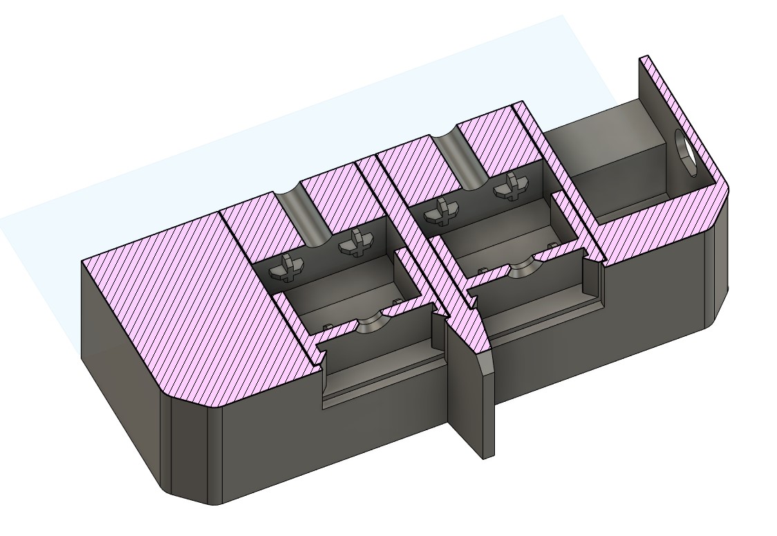
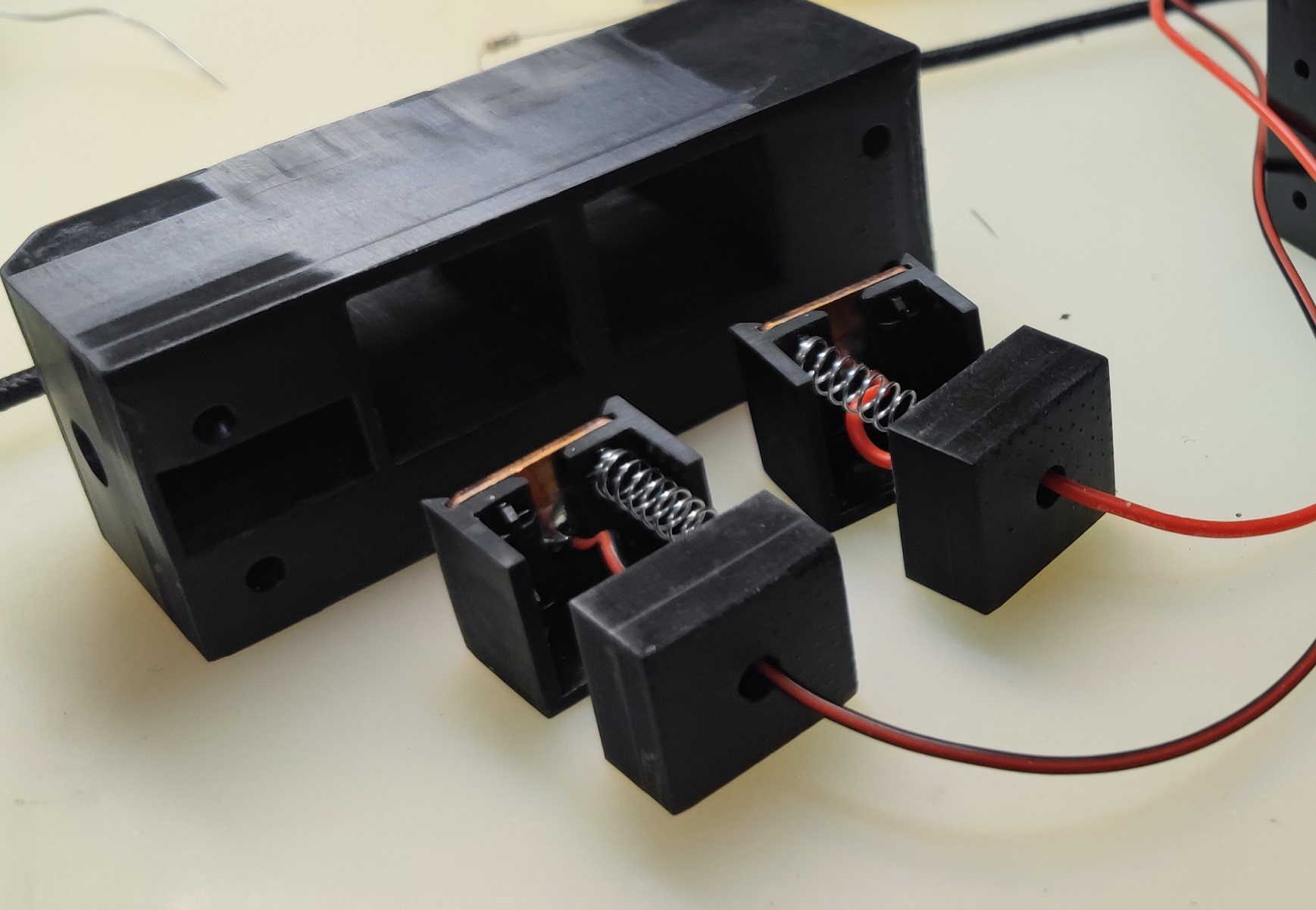
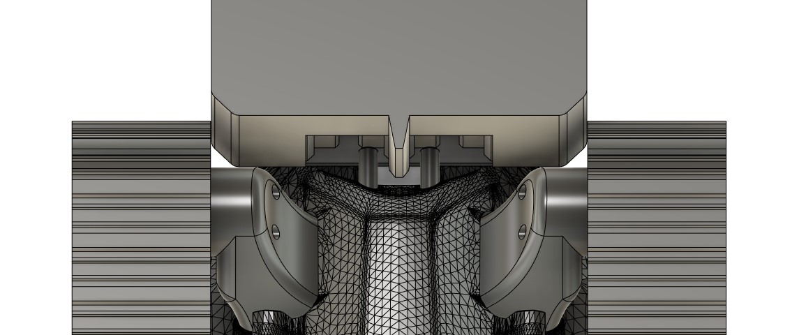
Рассматривал варианты магнитных контактов, но ввиду кажущейся сложности реализации же остановился на подпружиненных. В теле робота я разместил штифты, а на зарядной станции пластины. В целях экономии места пружины и индикация будут на стороне станции.
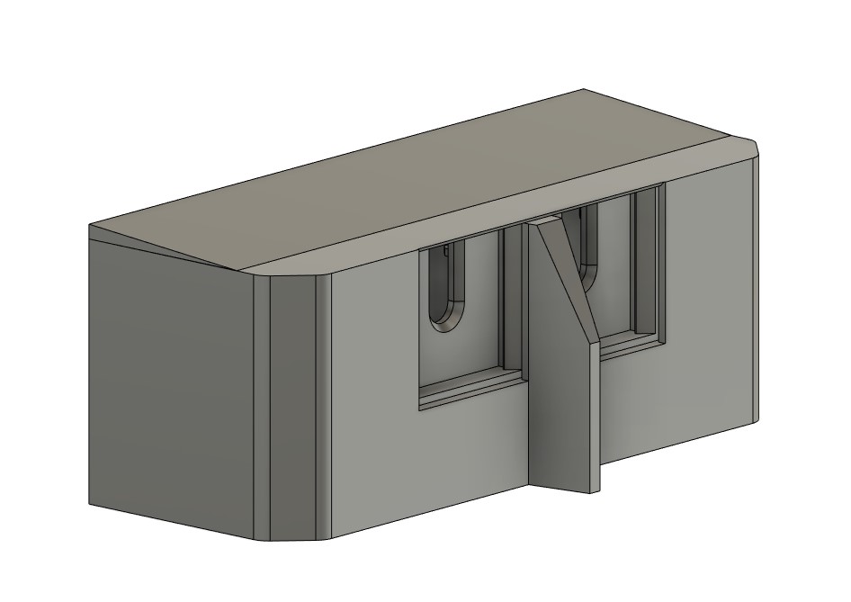
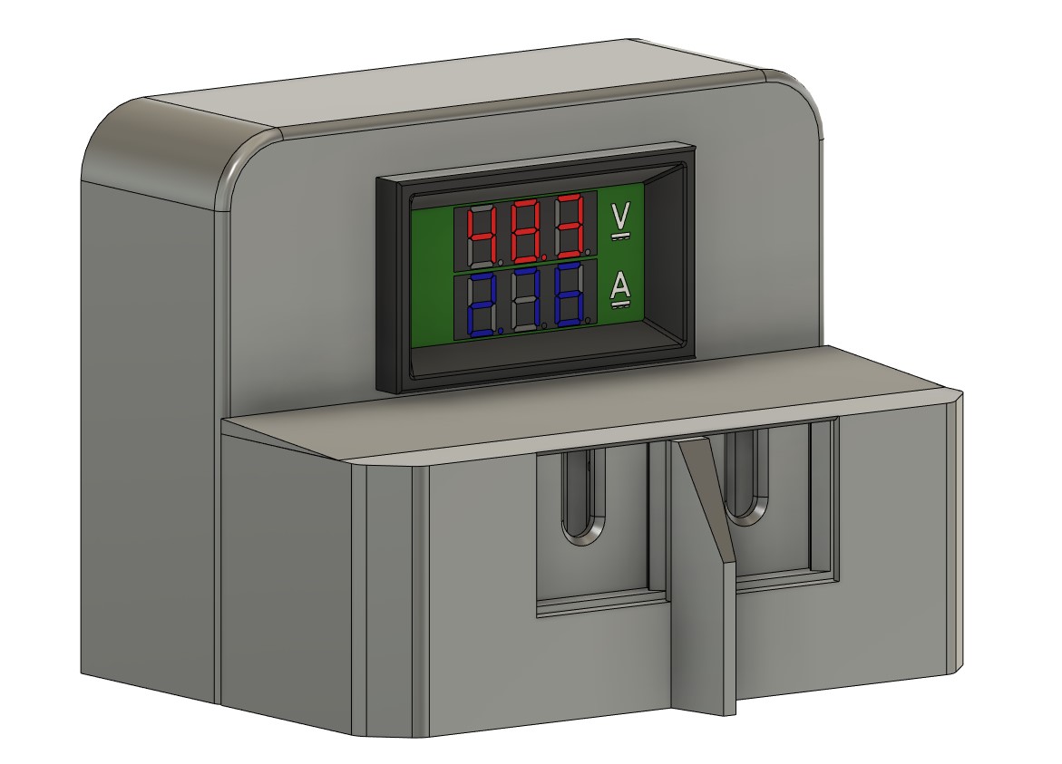
Руководствуясь все той же избыточной надёжностью были приобретены медный пруток 5мм и пластины 20х20х1.5мм. Под них и был спроектирован корпус:
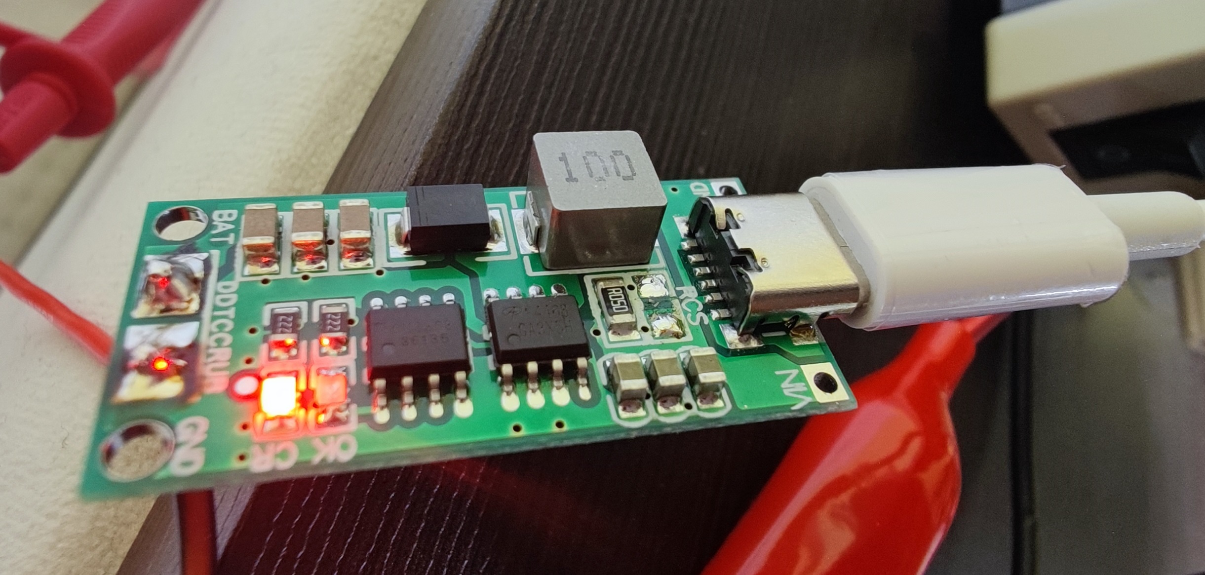
В качестве источника питания изначально планировал задействовать преобразователь 5v - 12.6v с usb type c на борту - характеристики обещали 3А тока:
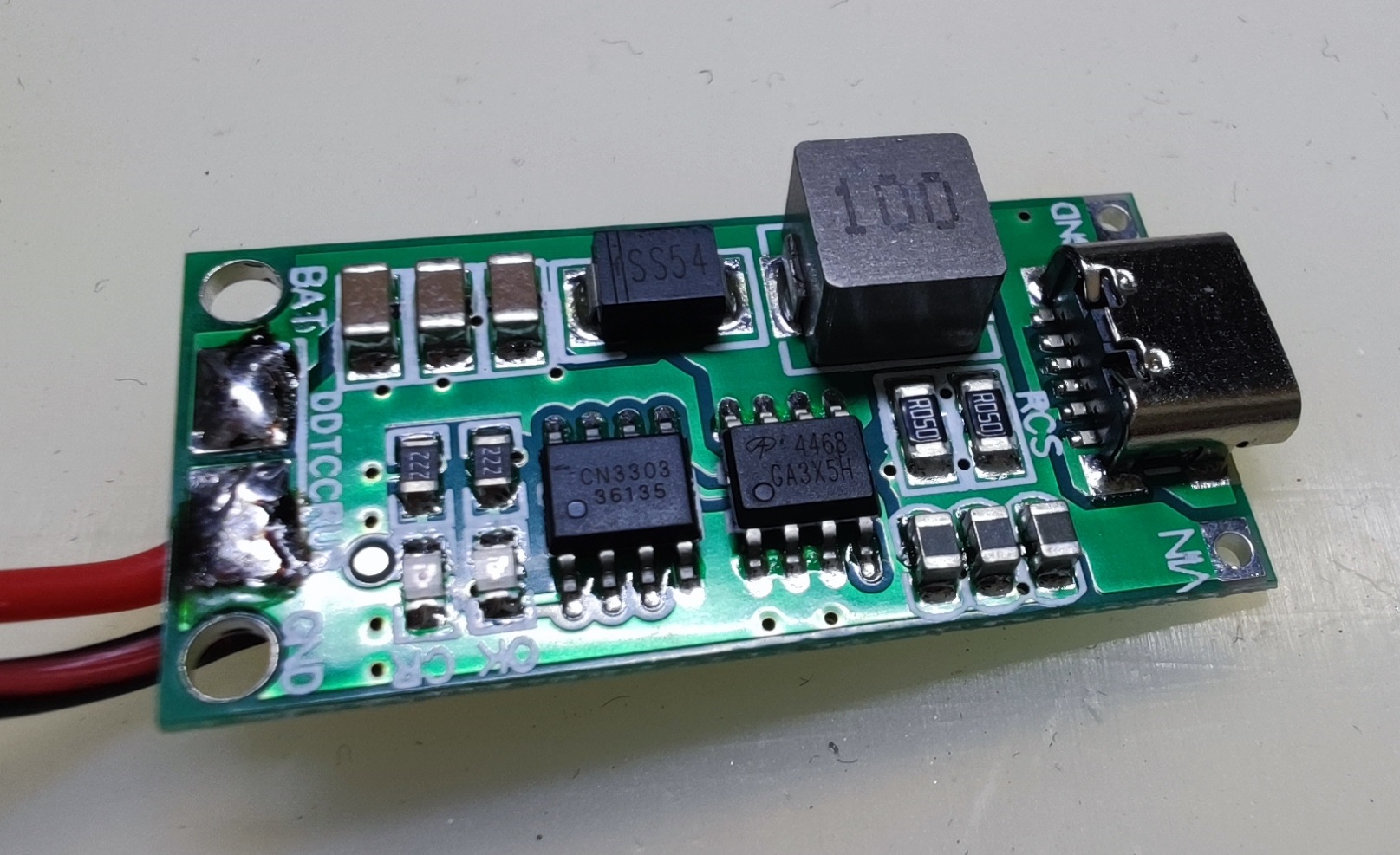
Но дьявол крылся в деталях - 3А не на выходе, а на входе, помимо этого плата в отсутствие активного охлаждения быстро перегревается и выходит из строя, попутно оплавляя все вокруг. Из отзывов было установлено, что мощность можно снизить вдвое, выпаяв один из реисторов у входа:
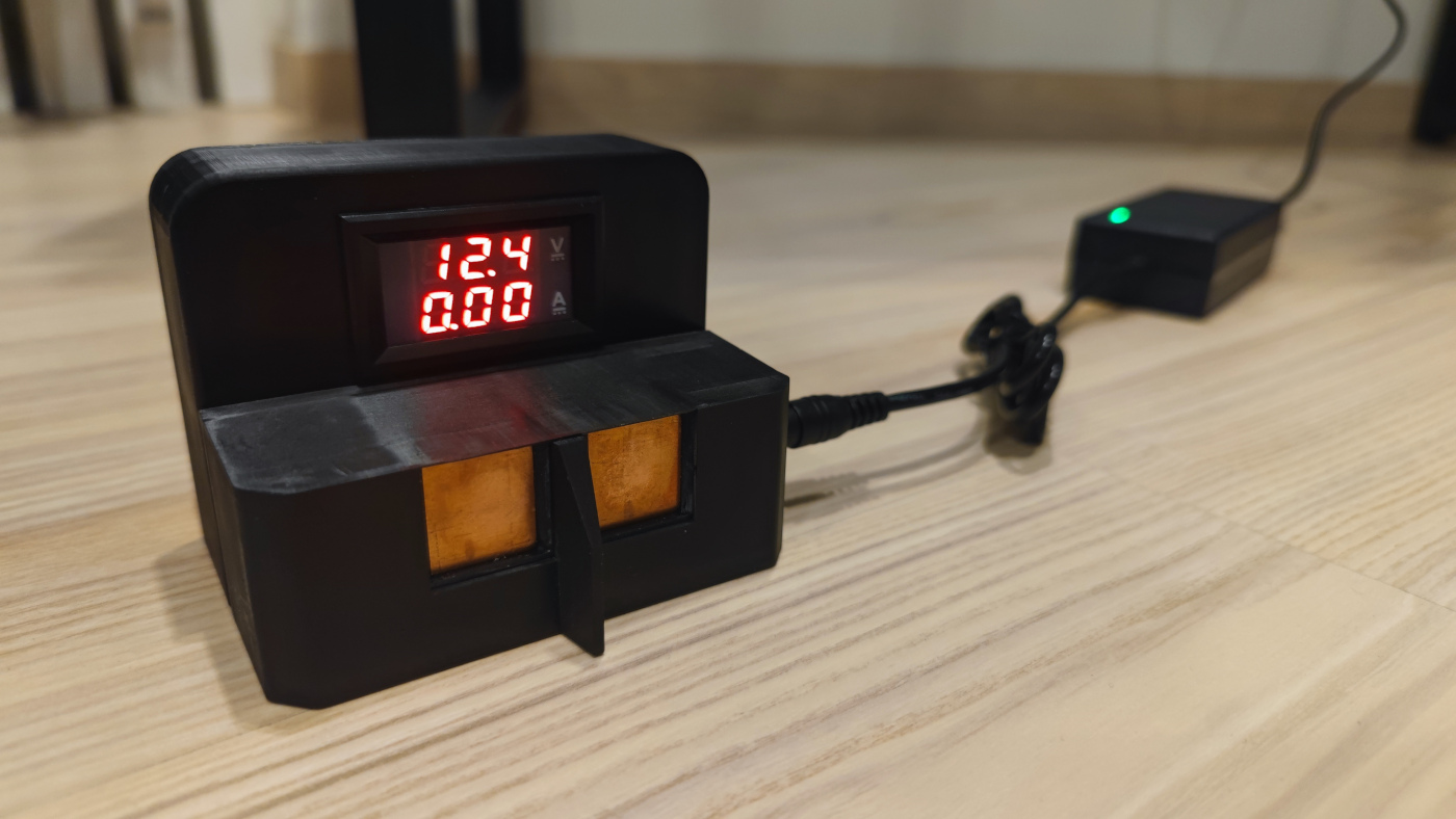
Но и это не спасло, плата выдавала меньший ток и не так быстро грелась, но за минуту грелась градусов до 70-80, оставлять такое без присмотра не решился. В итоге все свелось к нормальному внешнему блоку питания, подходящее гнездо для разъёма которого по счастливой случайности у меня нашлось в закромах.
Детали получилось подогнать достаточно плотно, но без люфта. Пластины на 1 пружине в углу со стороны штифта работают идеально.
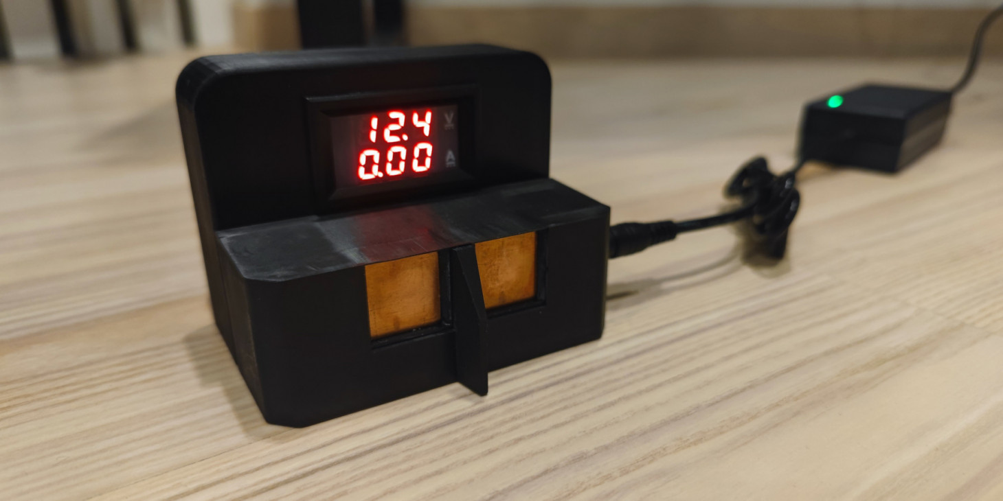
Что касается индикации - была идея собрать схему с 2 светодиодами, но, честно говоря, быстро не разобрался элементарной базой и принципиальной схемой, а время поджимало. Вместо них взял вольтамперметр и расположил на зарядной станции аккурат напротив камеры. По его показаниям будем определять статус заряда. Небольшой ток он, правда, не показывает и ориентироваться можно либо по падению напряжения, либо при большом разряде - уже на амперметр.
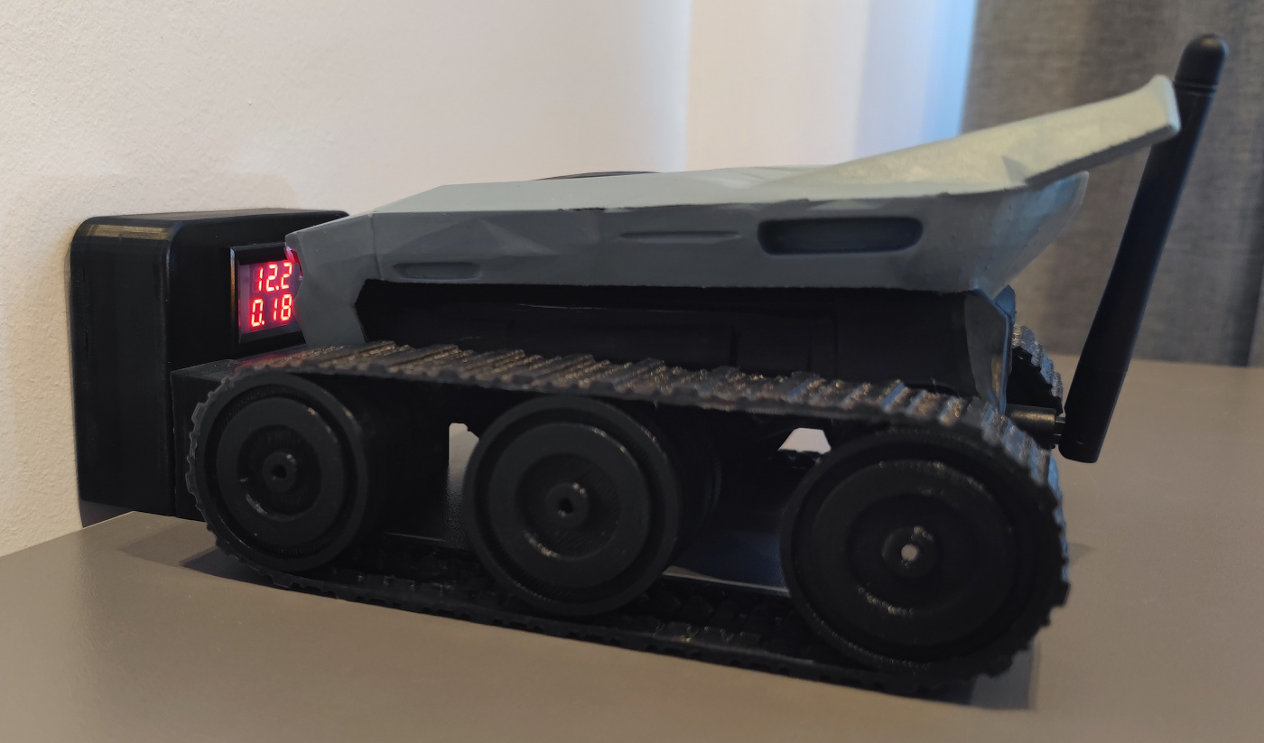
Финальный вид изделия таков:
Такой широкой станция спроектирована специально, чтобы сделать невозможным неправильный заезд на неё. Ширина на пару миллиметров меньше чем расстояние между траками:
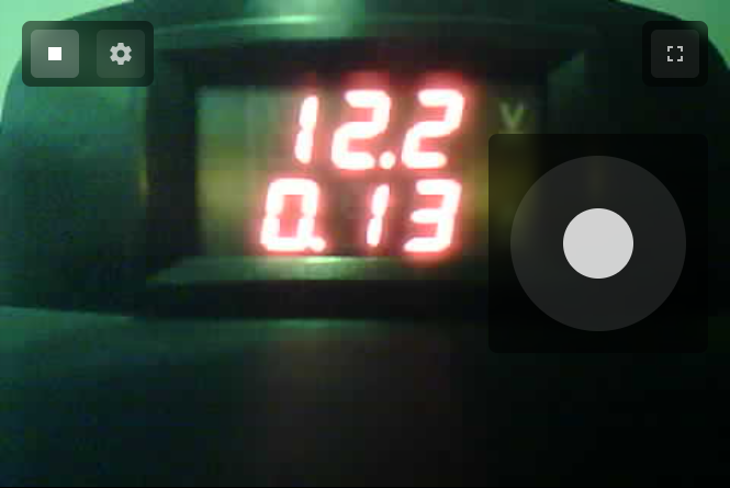
Ну и робот, стоящий на зарядке. Фокусное расстояние камеры не позволяет видеть все чётко, но для индикации такого вида достаточно.
Картинка в трансляции выглядит так (от разрешения не сильно зависит из-за фокуса, но здесь оно низкое):
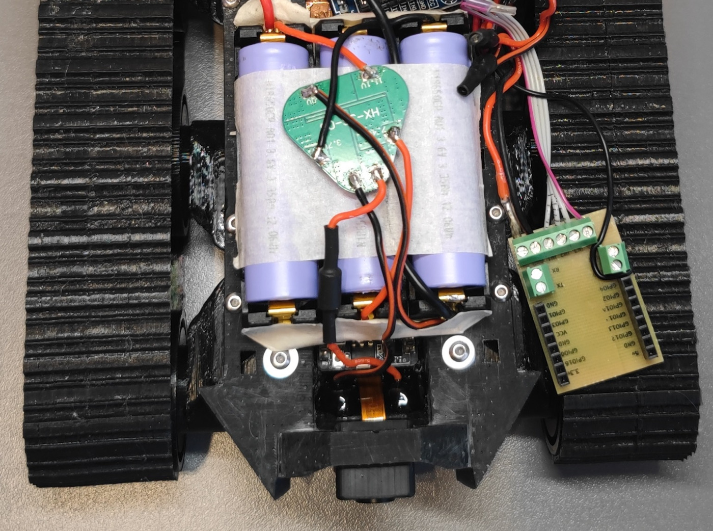
Что касается схемы зарядки - внутри стоит ещё 3S BMS плата, контролирующая заряд и обеспечивающая поддержание одинакового напряжения на банках. Можно было бы обойтись и без неё, многие заряжают 3s сборки напрямую, но я предпочитаю более безопасный вариант.
Из-за избыточной упругости пружин поставить робота на зарядку дело нетривиальное - он отпружинивает и остается без контакта, нужно ловить нужное положение. Думаю схема на магнитах, как у многих наручных часов, была бы легче в использовании. До её реализации я не добрался, возможно зарядную станцию будет ждать апгрейд.
Комментариев пока нет
-

Goback - простые бэкапы
Решил тут наконец заняться бэкапами. И без самописных утилит не обошлось. -

Проект Наблюдатель
Проект приурочен к хеллоуину - это статуя одноглазого ктулху с механизированным… -

Универсальный AI Telegram Bot
Хотите в пару действий запустить собственного AI бота для Telegram? -

Анализ истории просмотров Youtube
Задумывались, сколько времени вы проводите за просмотром видео? Давайте считать. -

Image2model с tripo3d и Blender
Иногда хочется, чтобы нарисованный или сгенерированный персонаж стал настоящим -

Локальный эмулятор Telegram
Писали ли вы когда-нибудь телеграм ботов?