603
Проект смотритель. Часть 3. Фоторезист
Эта статья является частью цикла
- Проект смотритель. Часть 1. Начало
- Проект смотритель. Часть 2. Дизайн
- Проект смотритель. Часть 3. Фоторезист
- Проект смотритель. Часть 4. Шасси
- Проект смотритель. Часть 5. Гусеницы
- Проект смотритель. Часть 6. Моделирование и печать
- Проект смотритель. Часть 7. Железо
- Проект смотритель. Часть 8. Софт
- Проект смотритель. Часть 9. Зарядная станция
- Проект смотритель. Часть 10. Bluetooth
- Проект смотритель. Часть 11. Home assistant
- Codex написал WASD управление для Смотрителя
Раз уж мы уже охватили (а запланировали еще больше) кучу технологий - почему бы не включить еще одну?
Решился на это спонтанно, подвернулась статья с упоминанием фоторезиста, паяльных масок и фотополимерного принтера.
Ранее был минимальный опыт проектирования и изготовления плат - проектировал в Spint Layout и воплощал методом ЛУТ (лазерно-утюжная технология), но раз уж техническая база позволяет - давайте пробовать что-то новое.
TL;DR; Инструкция по изготовлению платы фоторезистом на фотополимерном принтере
Если вам не интересен мой личный опыт, то вот к такому пайплайну я пришел в итоге:
- Подготовка файлов
- Выгружаем из KiCAD svg всех слоев: нужен негатив медного слоя, негатив маски и обычная шелкография. Важно чтобы внешний контур всех svg совпадал и у каждого слоя был общий центр, иначе не получится совместить маску.
- Конвертируем svg в stl через разработанный мной конвертор - https://github.com/positron48/svg2stl
- На фотополимерном принтере подготавливаем файлы печати - 10с засветка нижнего слоя, 6 нижних слоев. Центрируем детали в слайсере.
- Фоторезист
- Шлифуем медный слой 1000 наждачкой
- Обезжириваем спиртом
- Наклеиваем фоторезист
- Проглаживаем пару раз утюгом на режиме "синтетика" по 1-2 секунды
- На принтере собираем упоры по 2 направлениям, чтобы точно позиционировать плату
- Засвечиваем фоторезист на принтере 20 секунд
- Проявляем в растворе кальцинированной соды ~12 минут (250 мл воды, 1/2 чайной ложки кальцинированной соды)
- Дозасвечиваем фоторезист пару минут ультрафиолетом
- Травим плату в растворе (100мл 3% перекиси водорода, 3 чайных ложки лимонной кислоты с горкой, 1 чайная ложка соли, подогреть до 40℃)
- Паяльная маска
- Обезжириваем плату
- Наносим небольшое количество маски на плату (если есть сетка для шелкографии - пару шагов можно пропустить)
- Через прозрачную пленку распределяем маску равномерно по плате (руками, шпателем, стеклом)
- Заматываем плату пленкой и фиксируем её скотчек
- Засвечиваем на фотополимерном принтере 1 минуту
- Отрываем пленку и смываем спиртом незасвеченную маску (можно протирать ватной палочкой или тряпочкой)
- Дозасвечиваем маску еще несколько минут под УФ лампами
- Шелкография - полностью идентично кейсу с паяльной маской.
Собственно, что нам нужно для изготовления платы:
-
разведенная схема платы, на этот раз я взял KiCAD, смотрел еще на Eagle, но он доживает последние месяцы;
-
фольгированный текстолит;
-
фоторезист - существует в виде жидкости или пленки, но я взял сразу текстолит, покрытый фотополимерной пленкой - попробуем пропустить этап нанесения фотополимера на текстолит;
-
негативный пленочный фоторезист, если готового текстолита не нашлось;
-
кальцинированная сода - для проявки фотополимера;
-
лимонная кислота, перекись водорода и соль - для травления платы;
-
щелочь (Крот, средство для прочистки труб) - для смывания засвеченного фотополимера;
-
паяльная маска - то, что защищает основную часть платы и придает ей цвет;
-
сетка для шелкографии - чтобы нанести маску идеальным тонким слоем;
-
УФ лампа / светодиодная лента / бокс для засветки фотополимерных деталей - для окончательной засветки маски после проявки и смывания лишнего.
Еще я использую паяльный фен для разогрева платы, чтобы маска подсохла после нанесения и, собственно, фотополимерный принтер для засветки платы и маски.
KiCAD
Схема
KiCAD умеет переводить элементы со схем в платы с автотрассировкой, но у меня этого не вышло - часть деталей отсутствовала в библиотеке.
Да и схему я рисовал для всего устройства в целом, а плата выступает в роли шилда esp32-cam для подключения проводов к коннекторам.
Сама схема вышла такой:
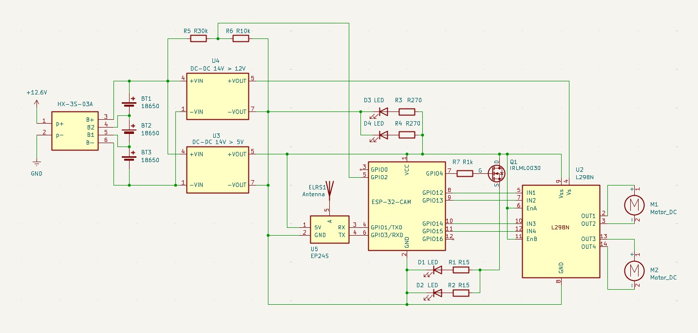
Разместил на ней вообще все, кроме адаптера питания, подключаемого к BMS плате зарядки (там USB-C плата с выходом в 12.6В).
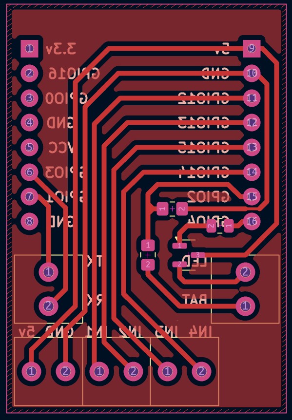
Плата
По обозначенным выше причинам всю плату пришлось рисовать руками. Возник еще странный баг (или непонятная фича) - если копировать компонент и вставить - то к копиям не цепляются дорожки.
Собственно, плата:
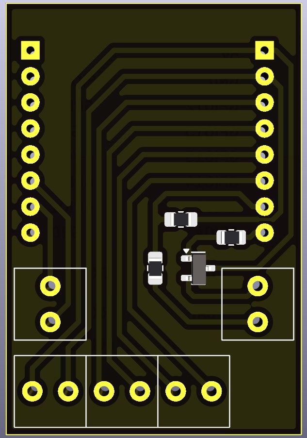
И её 3д-рендер. Были бы все элементы из библиотеки - KiCAD их бы и в 3d нарисовал, но пока только вот так:
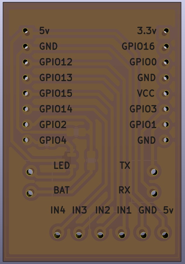
Фоторезист
Собственно, к самому сложному для первого раза, разобьем на шаги.
1. Подготовка файла для принтера
Вкратце изложу суть - у нас есть схема в KiCAD, из неё нам нужно по сути 2 слоя - медь и паяльная маска. Можно еще взять слой шелкографии и ЛУТом нанести его на лицевую сторону для корректной видимости подписей, но пока это кажется лишним.
Чертить негатив - SVG - выгружаем отдельно слой меди в негативе, слои маски и шелкографии в нормальном режиме.
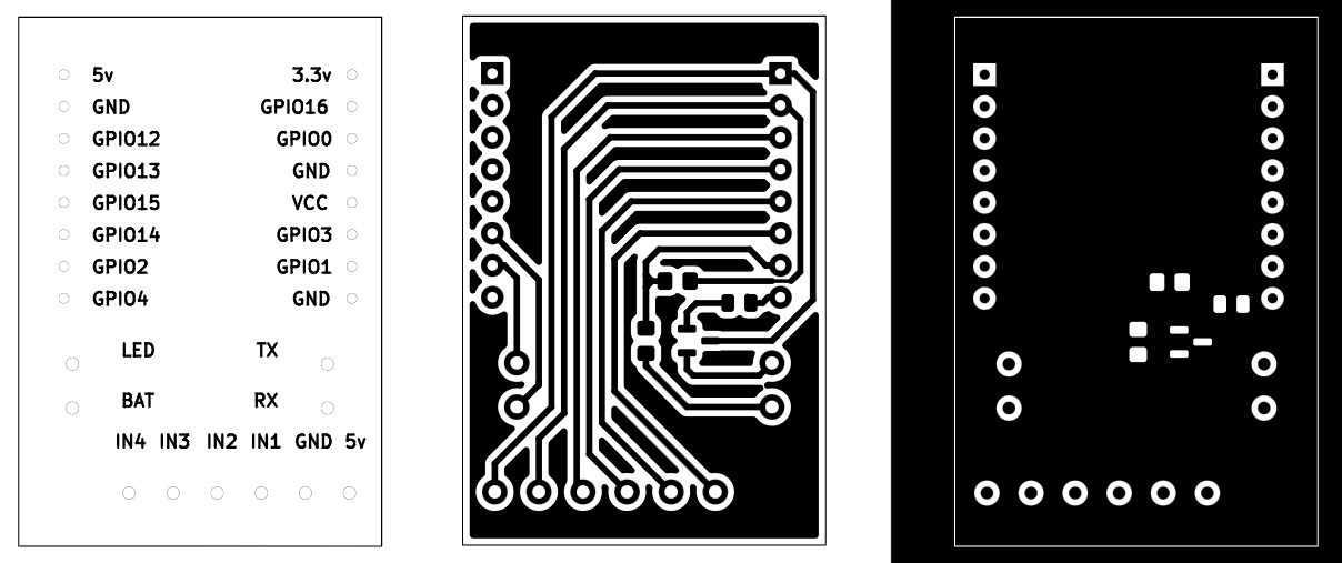
Дальше нам нужно как-то преобразовать эти svg в формат, понятный принтеру. Мой Photon Mono X6Ks не понимает ничего кроме своего собственного формата, поэтому нужно сделать stl модель. На просторах сети есть множество различных способов с кучей софта (фотошоп, различные CAD, UVTools и вот это все) - даже инструкции выглядят достаточно громоздко.
Но у нас же тут бум ИИ, а задача выдавливания SVG в STL кажется достаточно тривиальной. Несколько попыток ушло на то, чтобы заставить все это работать, в конечном итоге навайбкодилась утилита svg2stl написал Sonnet 3.7 Thinking в Cursor.
Единственное, что мне не удалось побороть - это сборку под Windows и устранение ложного определения exe файла как виру. Оказывается, Windows Defender распознает как троян собранные исполняемые файлы что через pyInstaller (запаковывает в архив исходники, интерпретатор питона и все зависимости), что через nuitka (транслирует исходники в Си и компилирует):
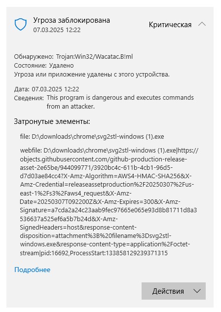
Если у кого-то есть желание это побороть - welcome в репозиторий. Также я не проверял запуск под Mac за неимением оного, но проблем быть не должно из-за его линуксоподобности.
Если кратко описывать, что происходит - SVG конвертируется в PNG. При этом параметром указывается физический размер пикселя, у меня для принтера это 0.034, меньше нет особого смысла делать - этот размер по факту влияет на DPI растрирования вектора и на физические размеры модели в STL. Далее не самым оптимальным образом по черным пикселям собираются прямоугольники и уже по ним происходит "выдавливание" на заданную толщину - т.е. генерируются все соответствующие полигоны.
Stl с размером пикселя в 0.034 выглядит так (дорожки 0.5мм):

2. Засветка фоторезиста
Существует позитивный и негативный фоторезист, мой купленный на готовой плате оказался позитивным. Текстолита хватило на 3 попытки, первая потерпела фиаско из-за позитивности, вторая из-за того, что я забыл обновить файл на флешке после инверсии, третий я засветил нормально, но в растворе кальцинированной соды он проявлялся настолько долго, что успел отойти даже в тех местах, в которых не должен был. Виной тому качество платы, фоторезиста, его нанесения или неподходящий раствор или параметры засветки - останется тайной, готовый текстолит закончился.
Заказывать новый и экспериментировать с подбором параметров не хотелось, поэтому я решил все же вернуться к канону и самостоятельной наклейке пленочного фоторезиста - закупил в Чип и Дип пленку, которой должно с запасом хватить на все эксперименты. Фоторезист негативный, на коробке есть инструкция, так что все должно быть хорошо.
На всякий поясню:
- негативный фоторезист - засвеченные области закрепляются, т.е. засвечивать нужно те части платы, которые должны быть покрыты медью;
- позитивные фоторезист - засвеченные области растворяются, т.к. засвечивать нужно те части платы, которые должны остаться без меди.
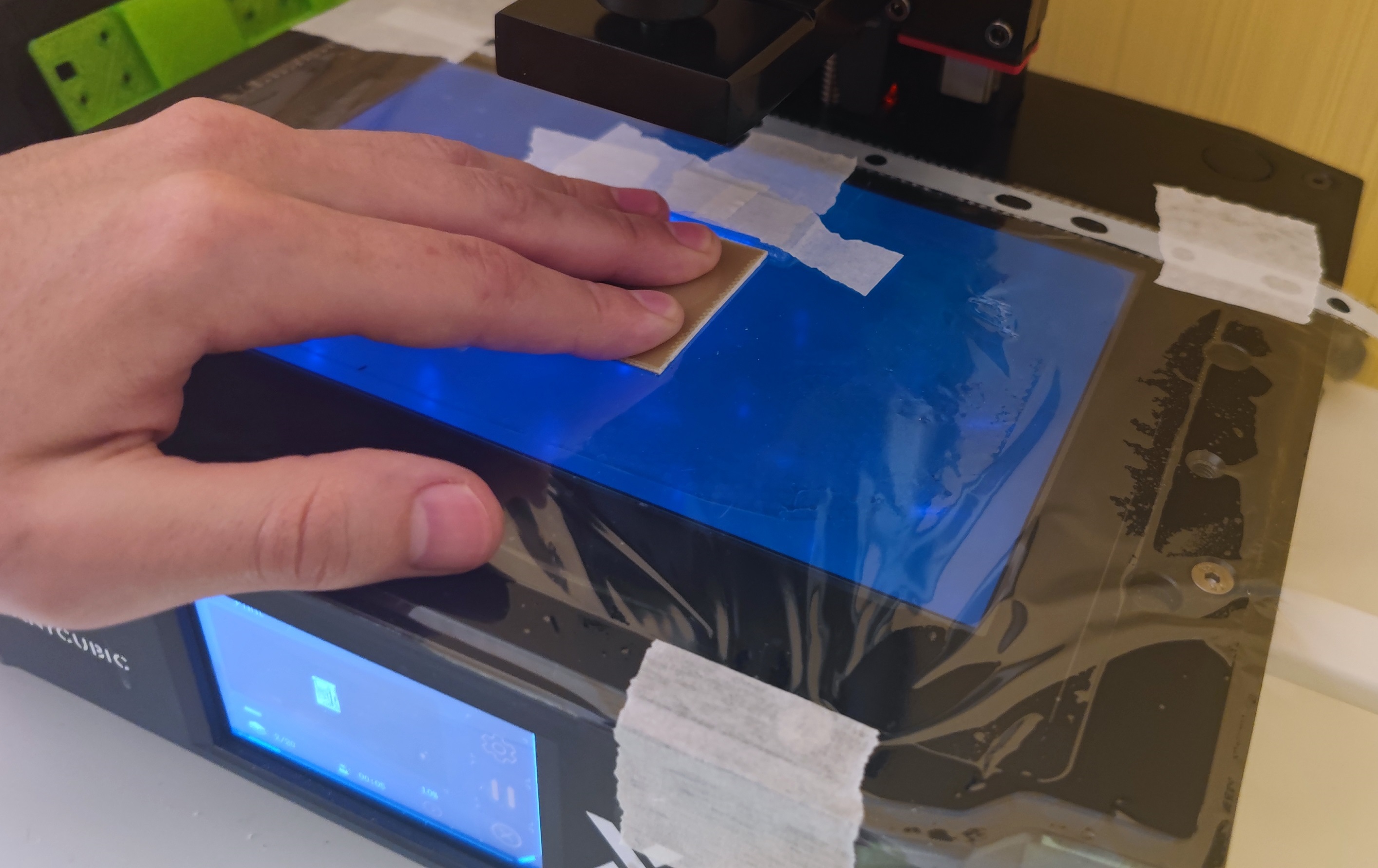
Засвечивал я на фотополимерном принтере (Photon Mono X6Ks) - для позиционирования платы соорудил нечто из пленки от "файла" для документов и прямоугольных пластин, оставшихся от тестирования принтера.
Размещал ничего не вымеряя, на глаз по картинке с принтера (это ультрафиолет, смотреть только через очки или камеру):
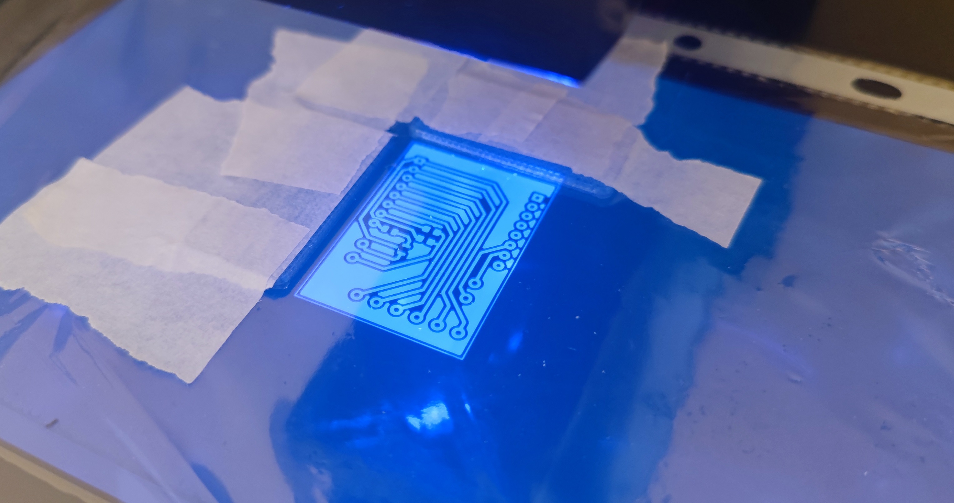
Кстати, если увидите нестыковки со схемой и масками выше - лайк за внимательность, изначально я неверно развел делитель напряжения.
Плату держал также руками, авось 20 секунд это делать несложно:
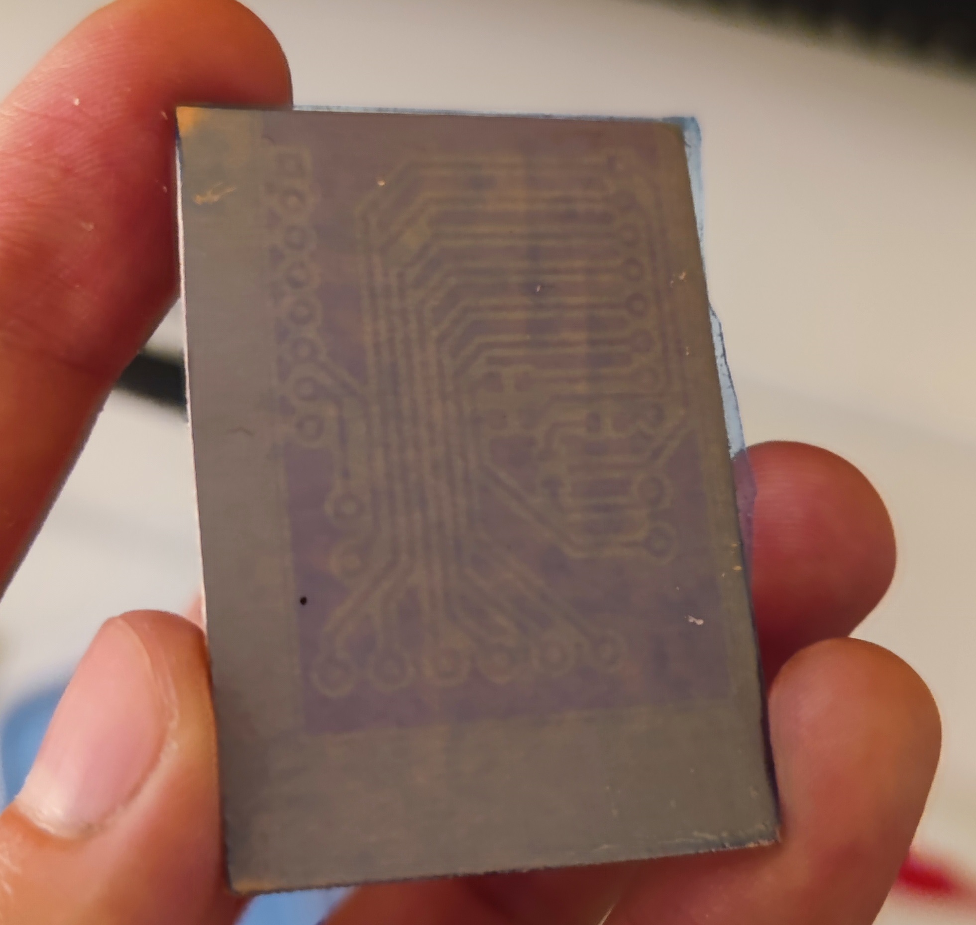
После засветки получаем какой-то невнятный рисунок, который должен стать более контрастным при проявке:
2.1 Нанесение пленочного фоторезиста
Мой фоторезист поставляется в виде пленки в рулоне - с обеих сторон есть защитные пленки. Определить где клеевой слой несложно, сложнее оторвать эти защитные пленки. В моем случае клеевой слой был лишь слегка липким, а верхний абсолютно гладким и не липким.
Из-за слабой клейкости удалось с первого раза наклеить пленку без пузырей, разглаживал просто руками, ламинатора у меня (пока?) нет. Далее прогрел получившуюся плату, прижатую к другой прищепками до ~100 градусов феном (так требовала инструкция). Этого оказалось достаточно, чтобы фоторезист нормально проявился даже с небольшим воздействием кисточки.
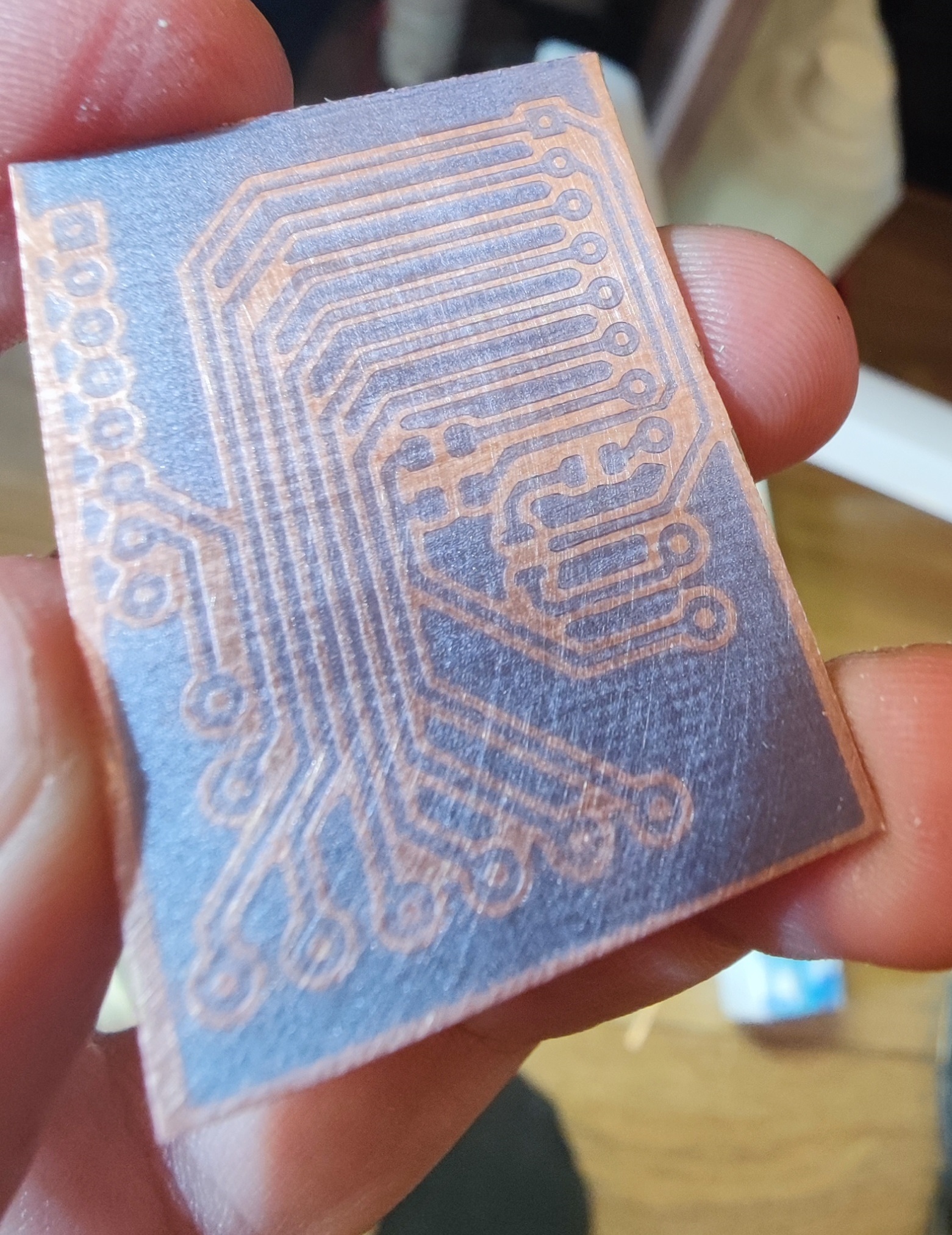
А вот для травления оказалось недостаточно - дорожки в процессе отвалились от платы.
При этом покрывал фоторезистом я кусок текстолита, которого было достаточно для изготовления 4 плат и на эту неудачную попытку ушла только четверть. Оставшиеся 3 я прогладил утюгом через бумагу на режиме для синтетики, фоторезист стал менее однородным, но явно схватился лучше.
И все равно последующая проявка оказалась неудачной - помогая процессу кисточкой я смахнул и дорожки, которые должны были быть закреплены.
Далее я с одной платой еще раз повторил тот же процесс засветки на 10с и закинул в проявку, а последнюю плату решил засветить подольше - 20с. Плата, засвеченная интенсивнее получила достаточно высокую контрастность и в сравнении с ней стало понятно, что фоторезист ранее смывался именно из-за недостаточного закрепления.
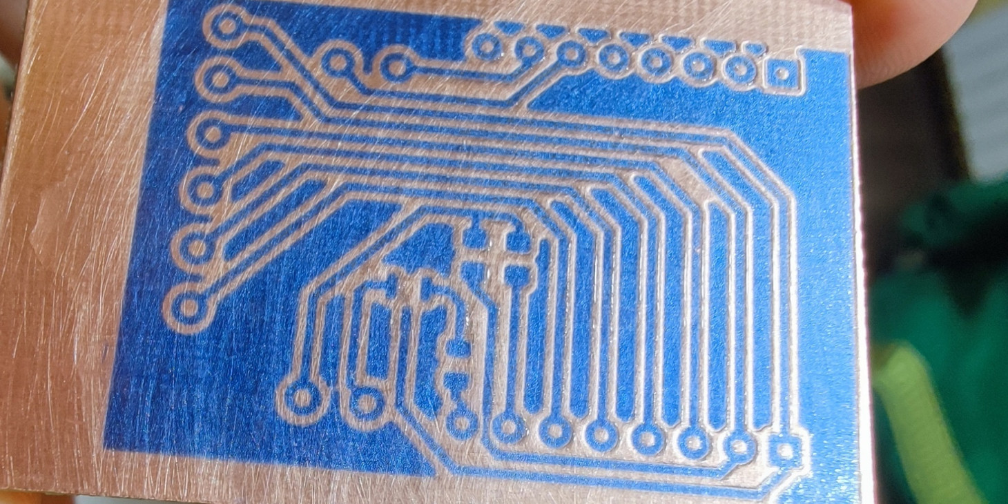
Собственно с этой платой и удалось дойти до финишного этапа.
3. Проявка
Проявку будем делать в растворе кальцинированной соды 1-2% (в бытовых магазинах можно найти килограмовую или около того пачку, обычно предназначается для стирки).
Рецепт раствора - на 250мл воды половину чайной ложки соды.
Пробовал это все подогревать, но что с подогревом, что без - проявка заняла около 12 минут. Здесь плата наполовину в проявочном растворе:
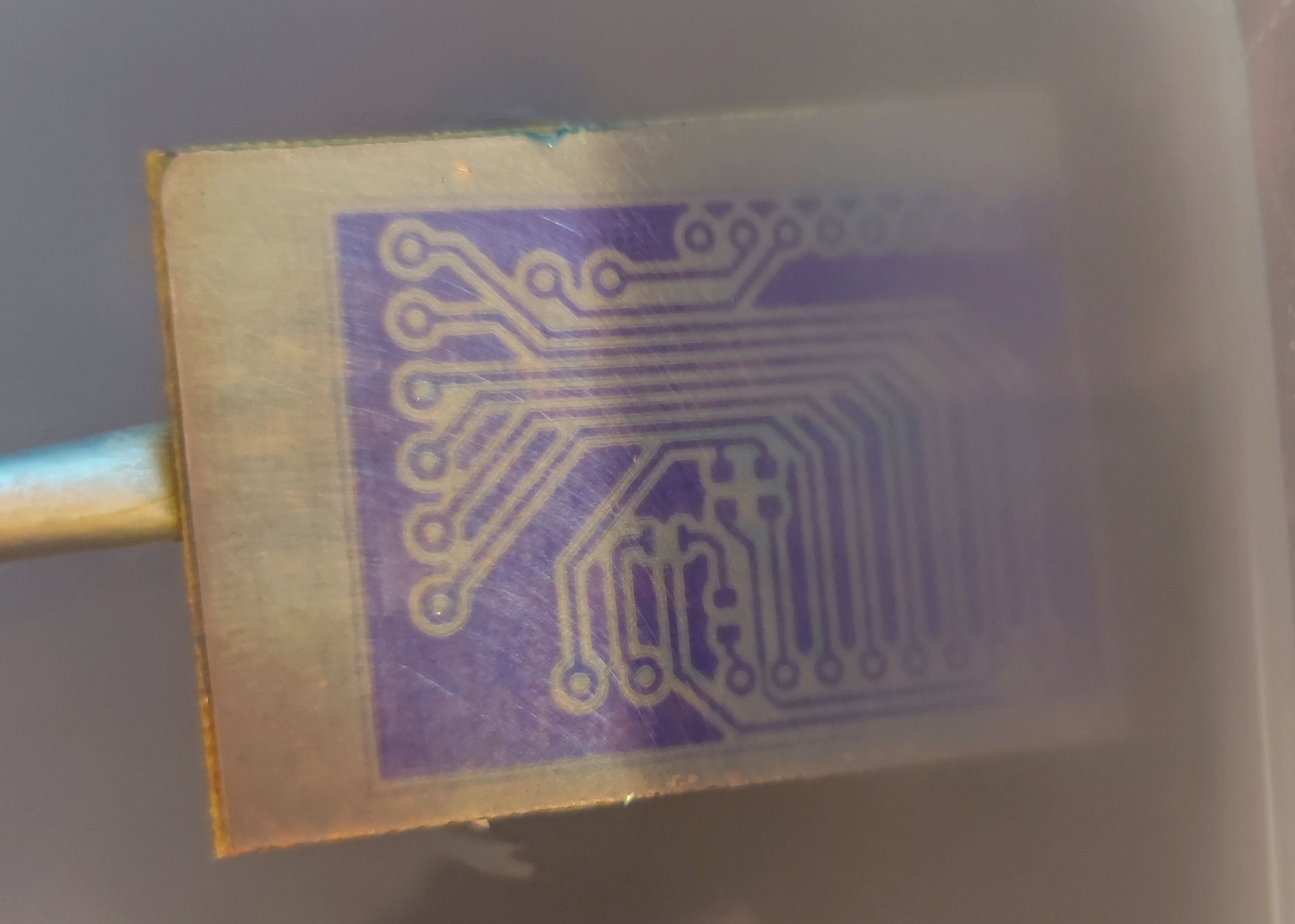
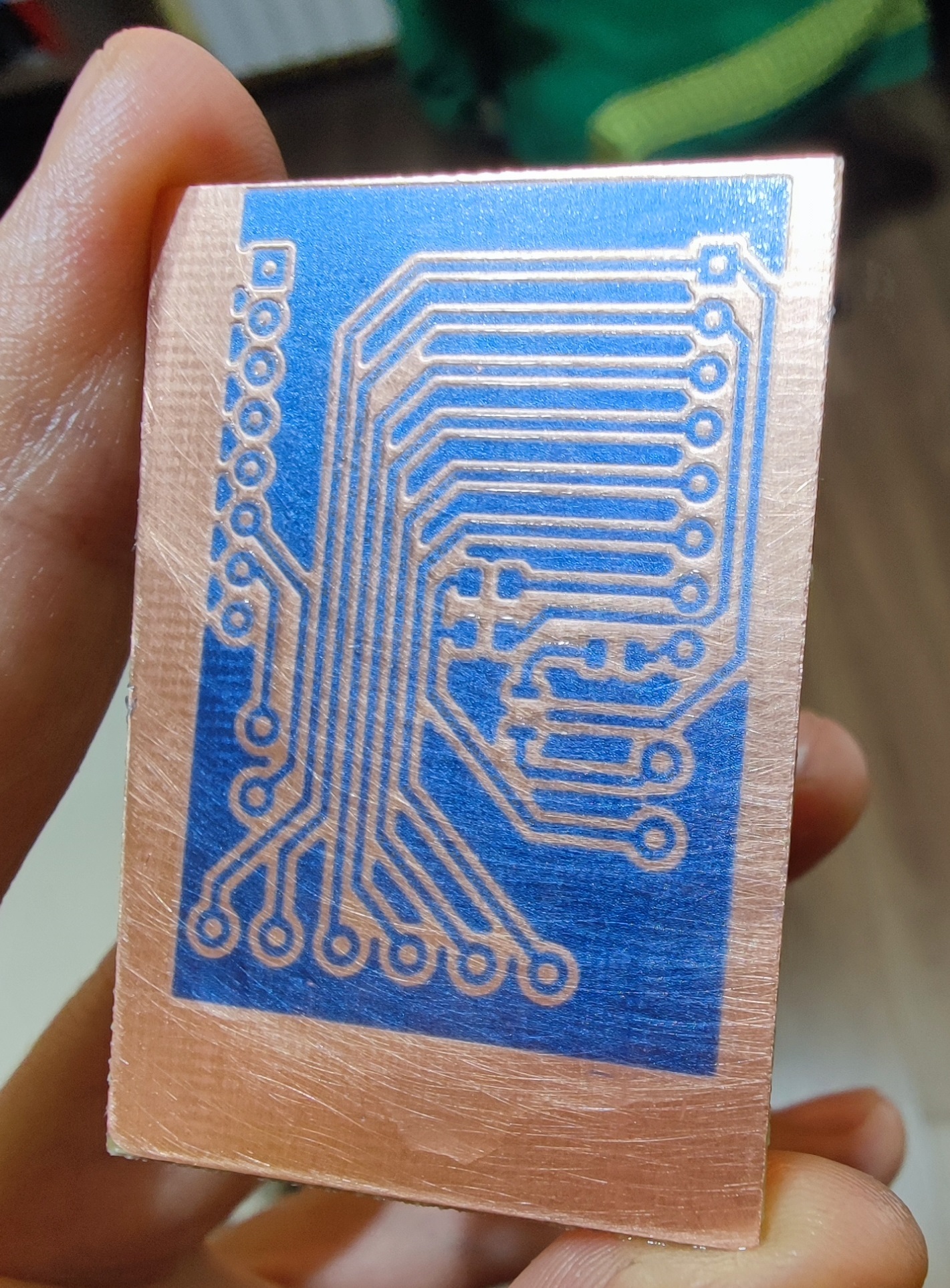
Как видите - проявилось все отлично, медь чистая. Если сомневаетесь в том, что вся пленка растворилась - подержите плату в растворе еще 10% времени от уже затраченного.
4. Травление
Кто-то после проявки сушит плату утюгом, кто-то ждет несколько часов, я решил дозасветить плату в своем импровизированном солярии 10 минут - по итогу контрастность значительно повысилась.
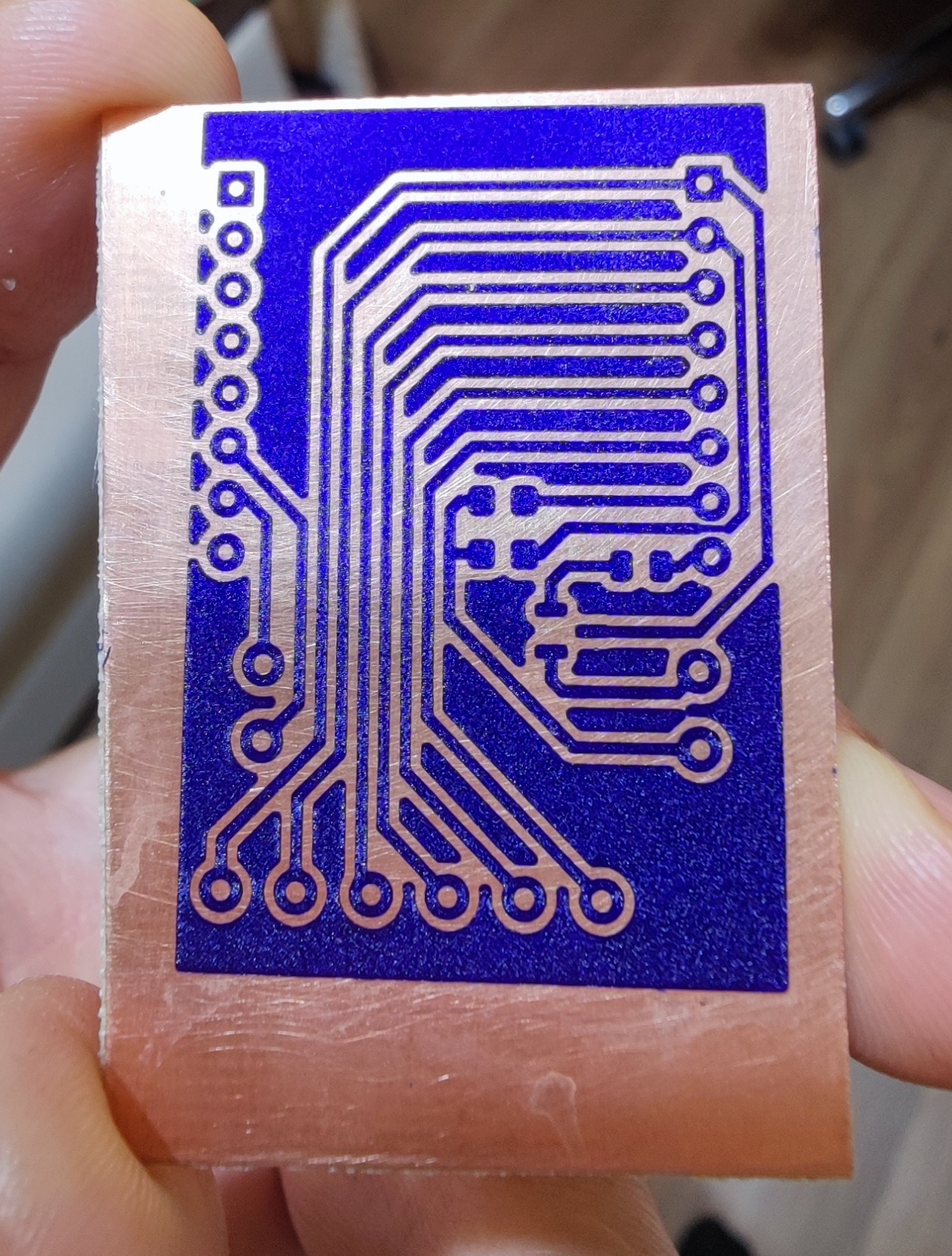
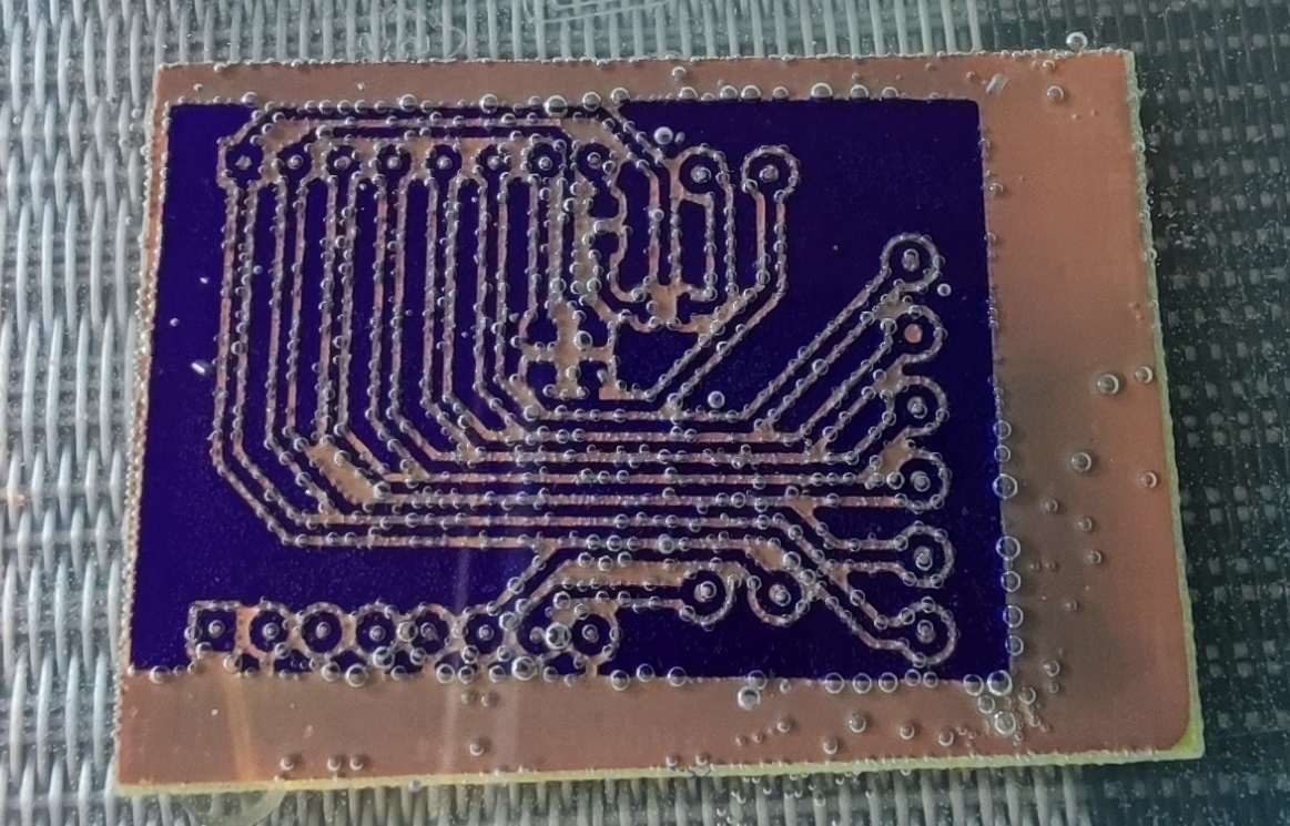
Травить будем в растворе перекиси и лимонной кислоты: 100мл 3% перекиси водорода, 3 с горкой чайных ложки лимонной кислоты, 1 чайная ложка соли. Желательно подогреть раствор до 40 ℃.
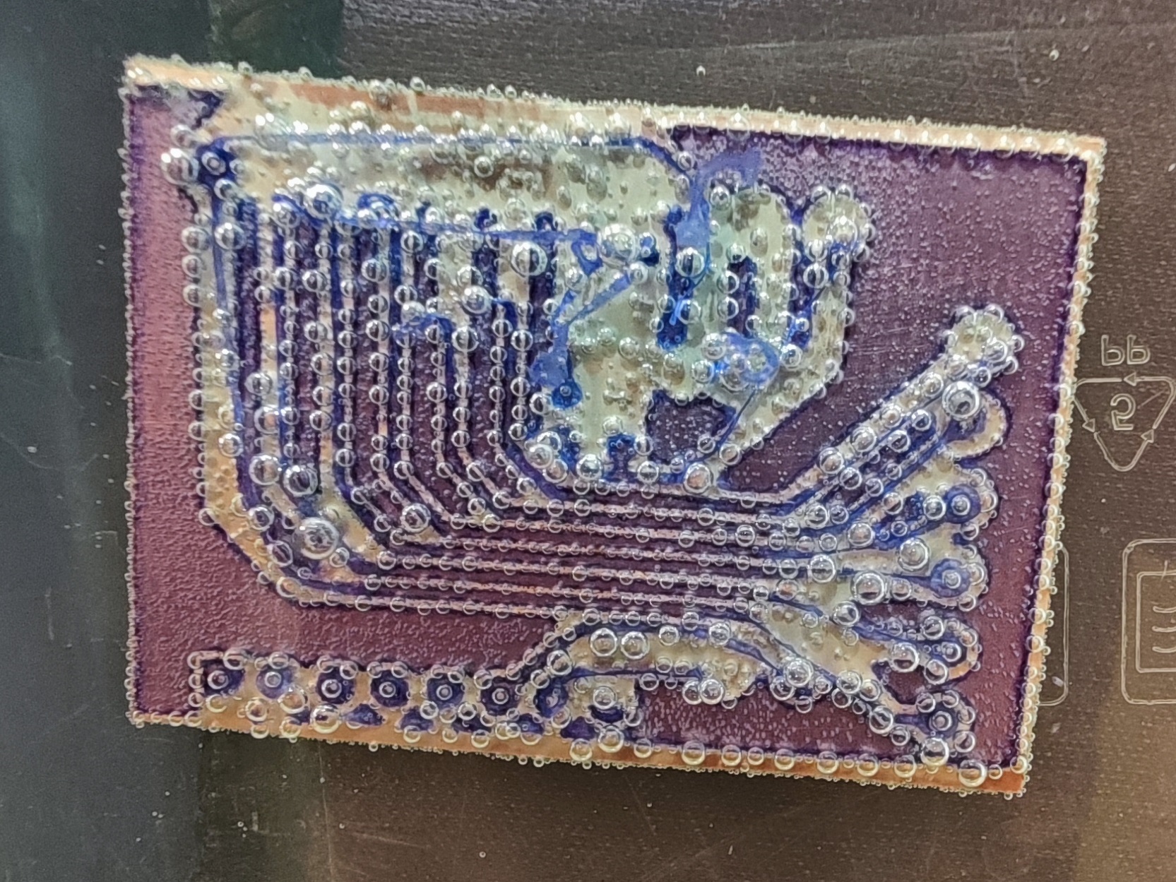
Просто кидаем плату и периодически помешиваем / вытаскиваем, чтобы образующиеся пузырьки не мешали процессу:
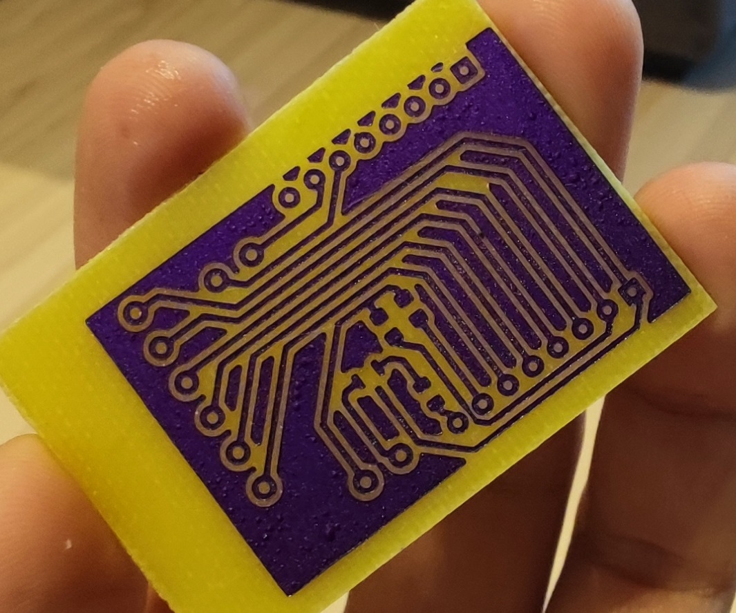
5. Смывание фоторезиста
Смыть можно в том же растворе кальцинированной соды, но я его к этому моменту зачем-то уже утилизировал, поэтому развел средство для прочистки труб (едкий натр, гидроксид натрия, "Крот") в небольшом количестве воды. Раствор очень опасен, работать нужно строго в перчатках - это концентрированная щелочь.
Собственно, в этом растворе фоторезист смывается буквально за минуту, я помогал ему ватной палочкой, но можно оставить плату и просто полежать.
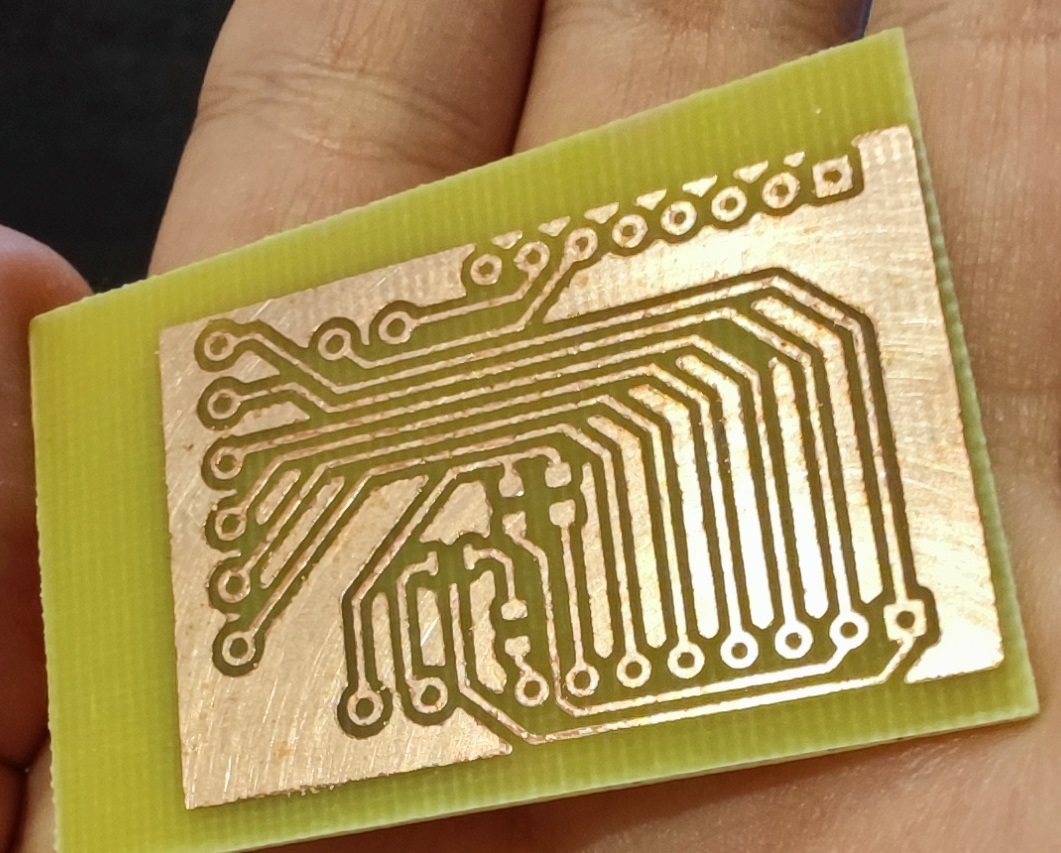
6. Маска
На этом можно и остановиться - залудить плату и запаять детали, но у нас же тут высокие технологии все же, чай не школьники - время попробовать еще и паяльную маску.
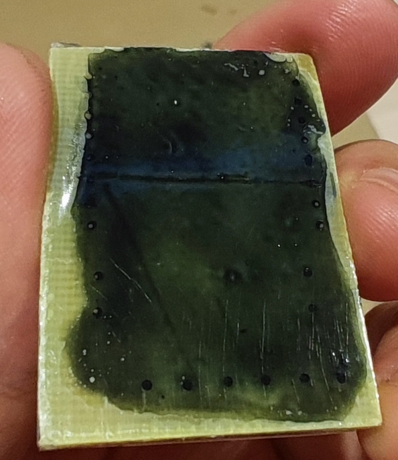
У меня это вот такой небольшой тюбик черной маски:
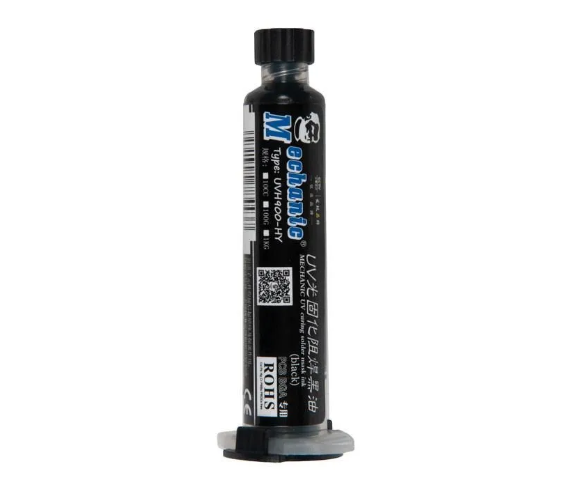
Увы, к моменту экспериментов мне еще не пришла сетка для шелкографии, через которую эту маску можно было бы нанести ровным тонким слоем - поэтому будем разгонять её под пленкой сами.
Фото процесса у меня нет, опишу текстом - обезжириваем плату, если успели заляпать или потрогать руками. Капаем некоторое количество пасты и накрываем сверху пленкой (это может быть лавсановая пленка, что-то потолще или, как у меня - часть "файла" для документов).
Можно придавливать сверху ровным стеклом для равномерного распределения. У меня такого не нашлось, поэтому распределял буквально руками - пальцами. Получилось не очень равномерно, но для первого раза думаю приемлемо.
Подождать высыхания маски на отлип я был не в силах, поэтому завернул пленку и закрепил скотчем.
Далее засвечиваем на принтере, позиционируя плату тем же образом, что при засветке фоторезиста. Но время экспонирования уже должно быть больше - я выдержал 50 секунд.
Т.к. маска еще не засохла - при снятии пленки незасвеченные участки снимаются легко, можно просто протереть чем-то, я смывал ватной палочкой в изопропиловом спирте.
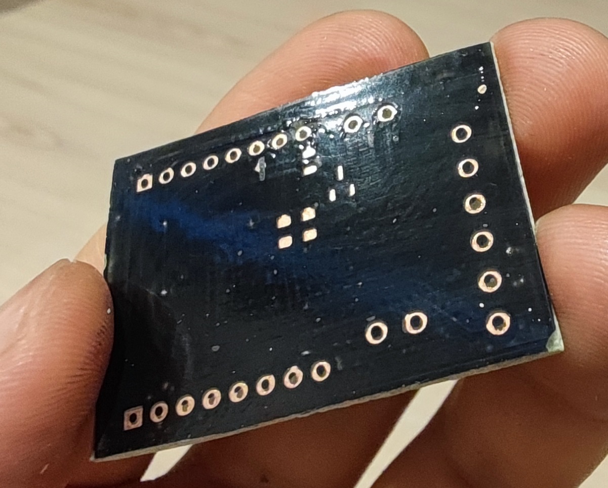
Где-то маска откололась, где-то есть небольшие просветы меди - это можно исправить зубочисткой или оставить так.
После смывки отправил на досветку в солярий еще минут на 10.
7. Шелкография
Надписи на обратную сторону изначально планировал либо не наносить, либо наносить ЛУТом, но раз эксперимент с маской увенчался успехом, то решил его повторить их здесь.
Процесс тот же, просто засвечивать будем только надписи.
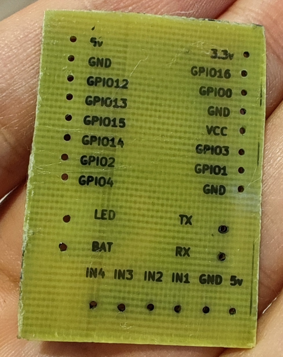
После смывания маски спиртом отправил еще на досветку на сколько-то минут в солярий.
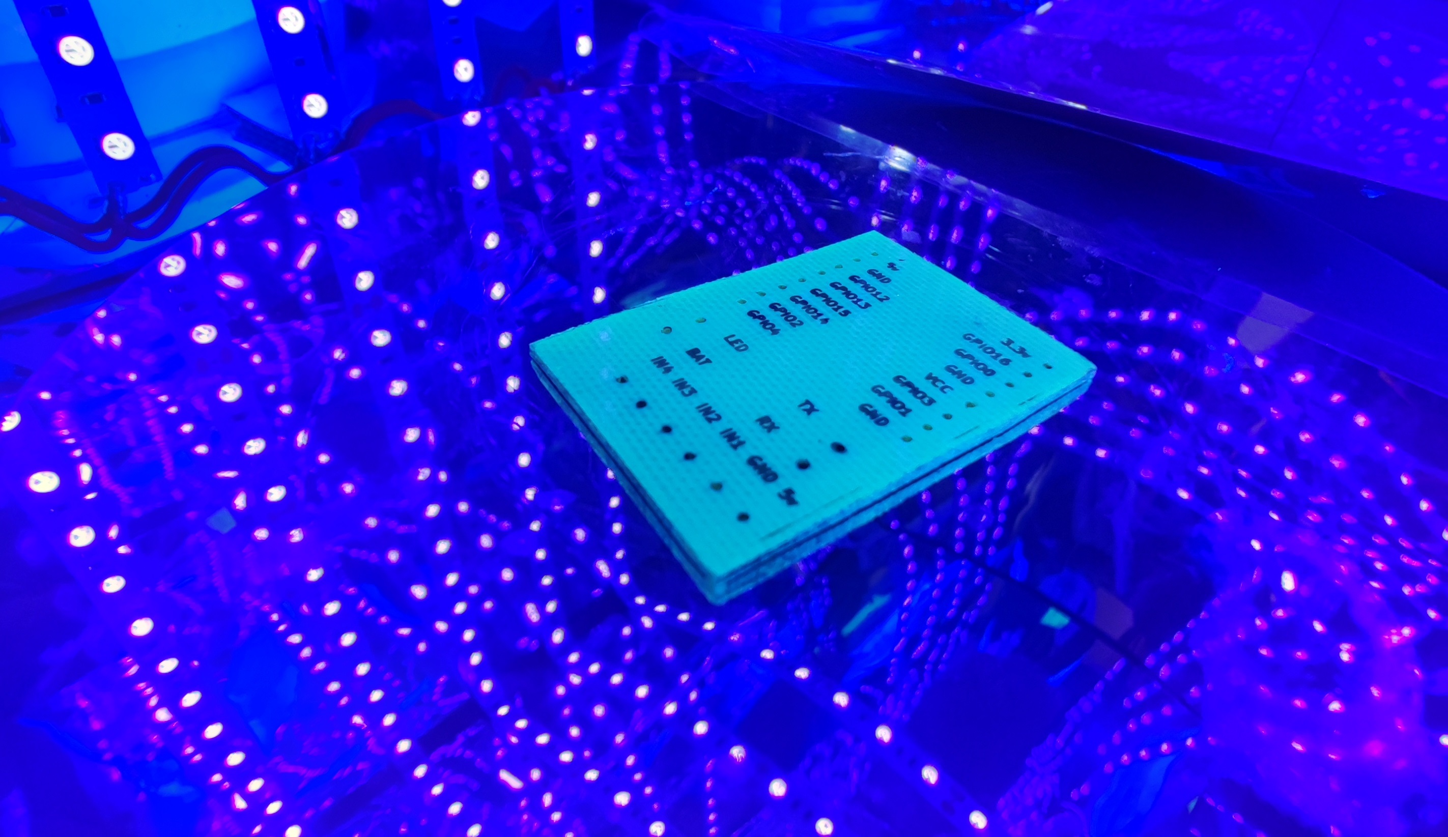
Есть 1 небольшой косяк с 5v - оторвался хвостик цифры, но это тоже можно поправить руками либо оставить как есть.
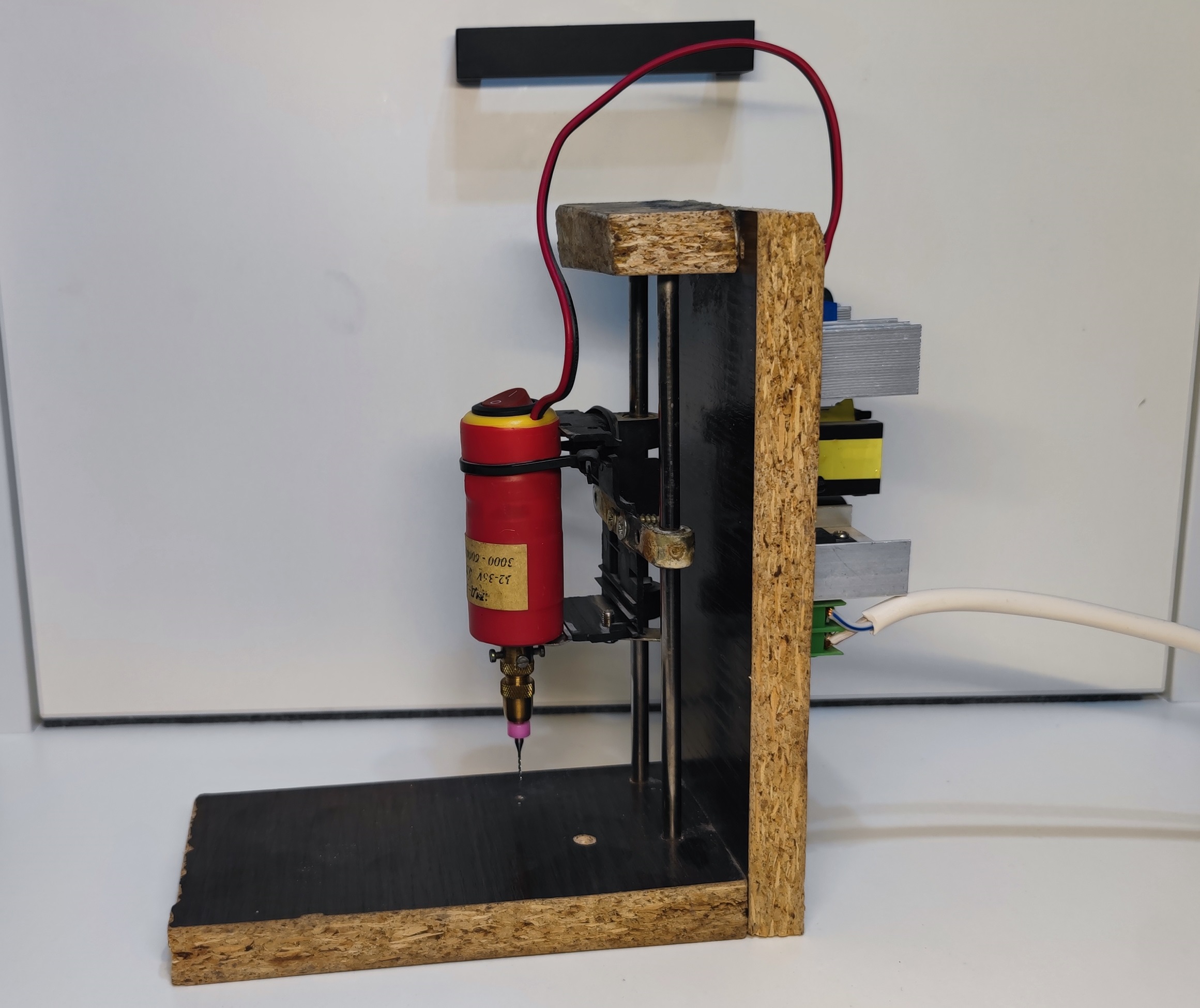
За кадром я еще насверлил отверстий сверлом 0.8 на самодельной сверлилке - лет 8 наверное пылилась в шкафу:
Ну и собственно всё, осталось запаять детали и потестировать (мультиметром прозванивал - все ок). Еще одну технологию можно считать освоенной, причем времени ушло не так много - управился за выходные.
Плата изготавливалась для моего проекта Caretaker - с другими технологиями и проектом в целом можете ознакомиться в серии статей.
Комментариев пока нет
-

Goback - простые бэкапы
Решил тут наконец заняться бэкапами. И без самописных утилит не обошлось. -

Проект Наблюдатель
Проект приурочен к хеллоуину - это статуя одноглазого ктулху с механизированным… -

Универсальный AI Telegram Bot
Хотите в пару действий запустить собственного AI бота для Telegram? -

Анализ истории просмотров Youtube
Задумывались, сколько времени вы проводите за просмотром видео? Давайте считать. -

Image2model с tripo3d и Blender
Иногда хочется, чтобы нарисованный или сгенерированный персонаж стал настоящим -

Локальный эмулятор Telegram
Писали ли вы когда-нибудь телеграм ботов?