415
Проект смотритель. Часть 4. Шасси
Эта статья является частью цикла
- Проект смотритель. Часть 1. Начало
- Проект смотритель. Часть 2. Дизайн
- Проект смотритель. Часть 3. Фоторезист
- Проект смотритель. Часть 4. Шасси
- Проект смотритель. Часть 5. Гусеницы
- Проект смотритель. Часть 6. Моделирование и печать
- Проект смотритель. Часть 7. Железо
- Проект смотритель. Часть 8. Софт
- Проект смотритель. Часть 9. Зарядная станция
- Проект смотритель. Часть 10. Bluetooth
- Проект смотритель. Часть 11. Home assistant
- Codex написал WASD управление для Смотрителя
Дисклеймер: я не имею отношения к машиностроению, робототехнике, промышленному дизайну и соответствующие дисциплины вроде сопромата и метрологии прошли мимо. Поэтому при проектировании я руководствуюсь принципом избыточной надёжности.
А теперь мы будем изобретать колесо. Большие надежды я возлагал на 3д печать, забегая вперёд - не прогалал, все что было возможно напечатать, включая гусеницы, было напечатано.
В качестве двигателей для небольших устройств выбор как будто не очень большой.
Есть моторчики без редукторов, для которых ещё нужно его собрать - такие стоят в Rover 5.
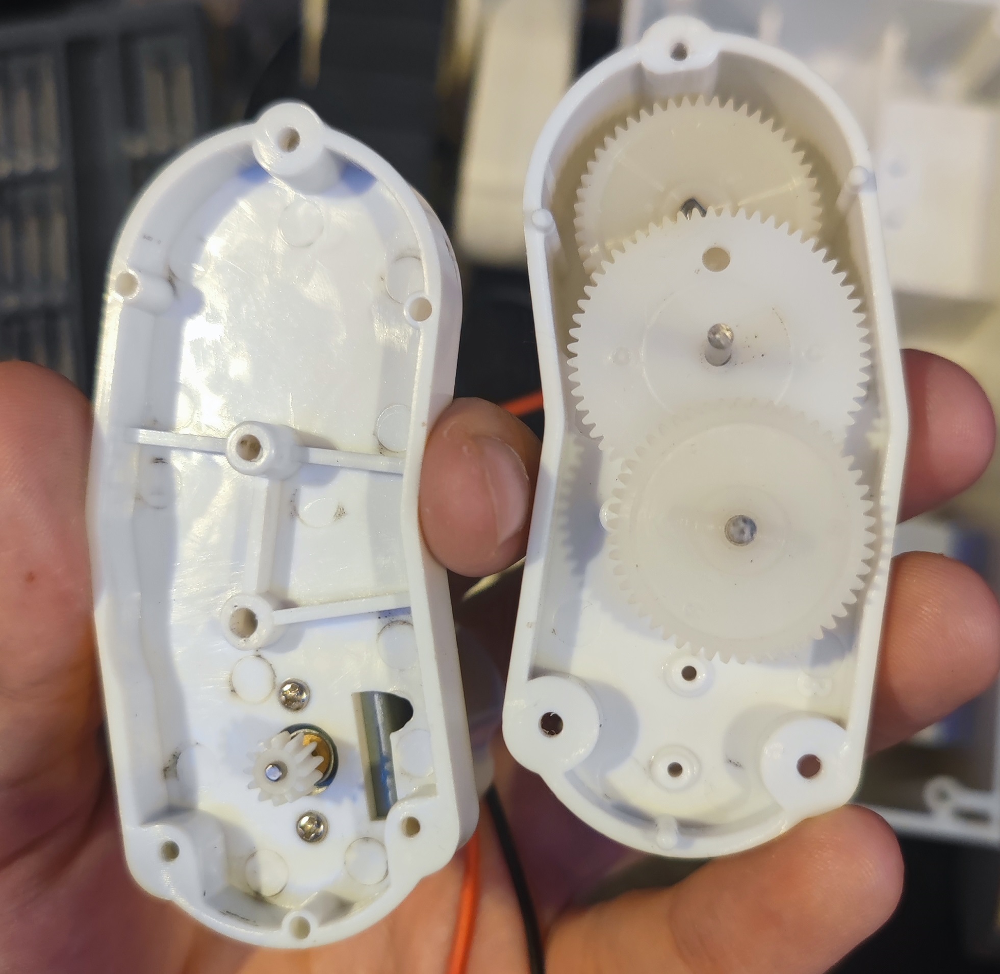
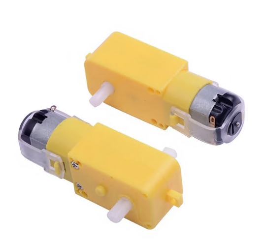
Есть моторчики с редуктором различных форматов, но с пластиковыми шестернями и выходными валами.
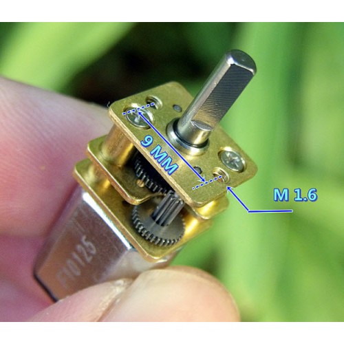
Ну и есть моторчик с полностью металлическими редукторами - GA-12-N-20, есть различные варианты по передаточным числам, нам подходит.
По картинке на меркетплейсах даже с размерами сложно было осознать, насколько он окажется маленьким:
Обычно в гусеничных шасси двигатели стоят внутри корпуса, а ролики вращаются на их осях. Но я не придумал ни как избавиться от бокового перекоса ролика при натяжении (в Rover 5 таковой присутствует) ни как удлинить ось.
Зато я прикинул, что моторчик с осью и редуктором в длину аккурат равен планируемой ширине гусениц. А дальше подумал, что было бы интересно сделать колесо вокруг моторчика.
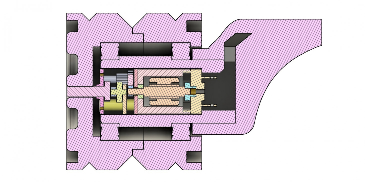
А чтобы не дать ни шанса на перекос - моторчик будет сидеть на 2 подшипниках. Осталось определиться с их типоразмером и компоновкой.
Изначально я заказал подшипники минимального размера, внутрь которых бы помещался моторчик - 6802 (15x24x5мм). Но не учёл, что редуктор моторчика не вписывается в габариты и внутрь не поместился. Поэтому компоновка могла быть только такой:
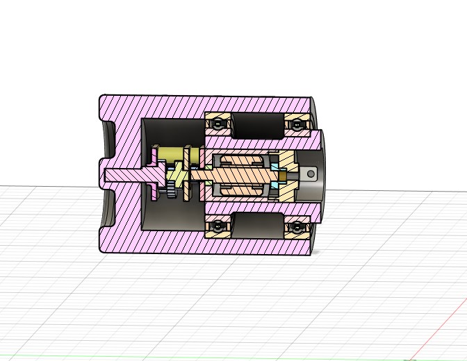
Такой вариант не очень подходил под мои критерии надёжности, хотя и был теоретически работоспособным. Поэтому подшипники были заменены на следующие по размеру - 6803 (17х26х5мм), а эти составлены для колёс без двигателей.
Еще несколько итераций ушло на подгон зазоров для сборки и на усовершенствование внешней части колеса.
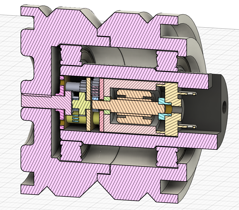
Также можно заметить, что модификация коснулась и устройства самого колеса - появились канавки под гусеницы, а также внешняя оболочка была разделена на стыкуемые части, которые фиксируют все части на своих местах - так проще и печатать и собирать, да и удерживаться вместе части должны за счет посадки и гусеницы, так что и крепление должно быть вполне надежное.
Опытным путем подобрал зазоры для безлюфтовой посадки - колесо собирается с усилием, но руками.
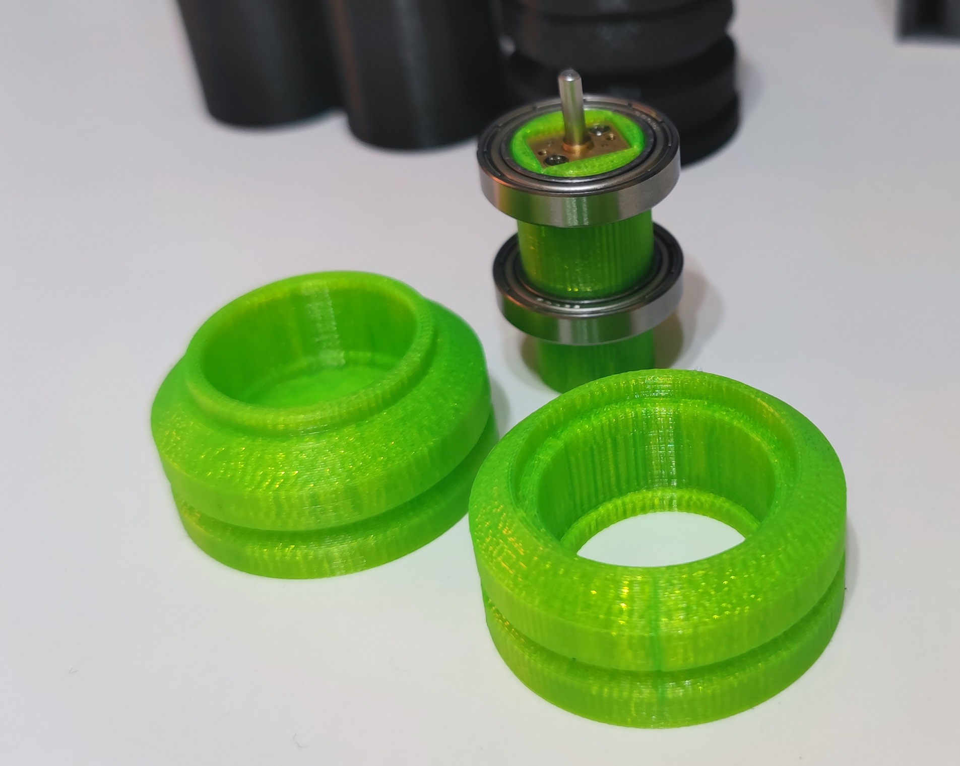
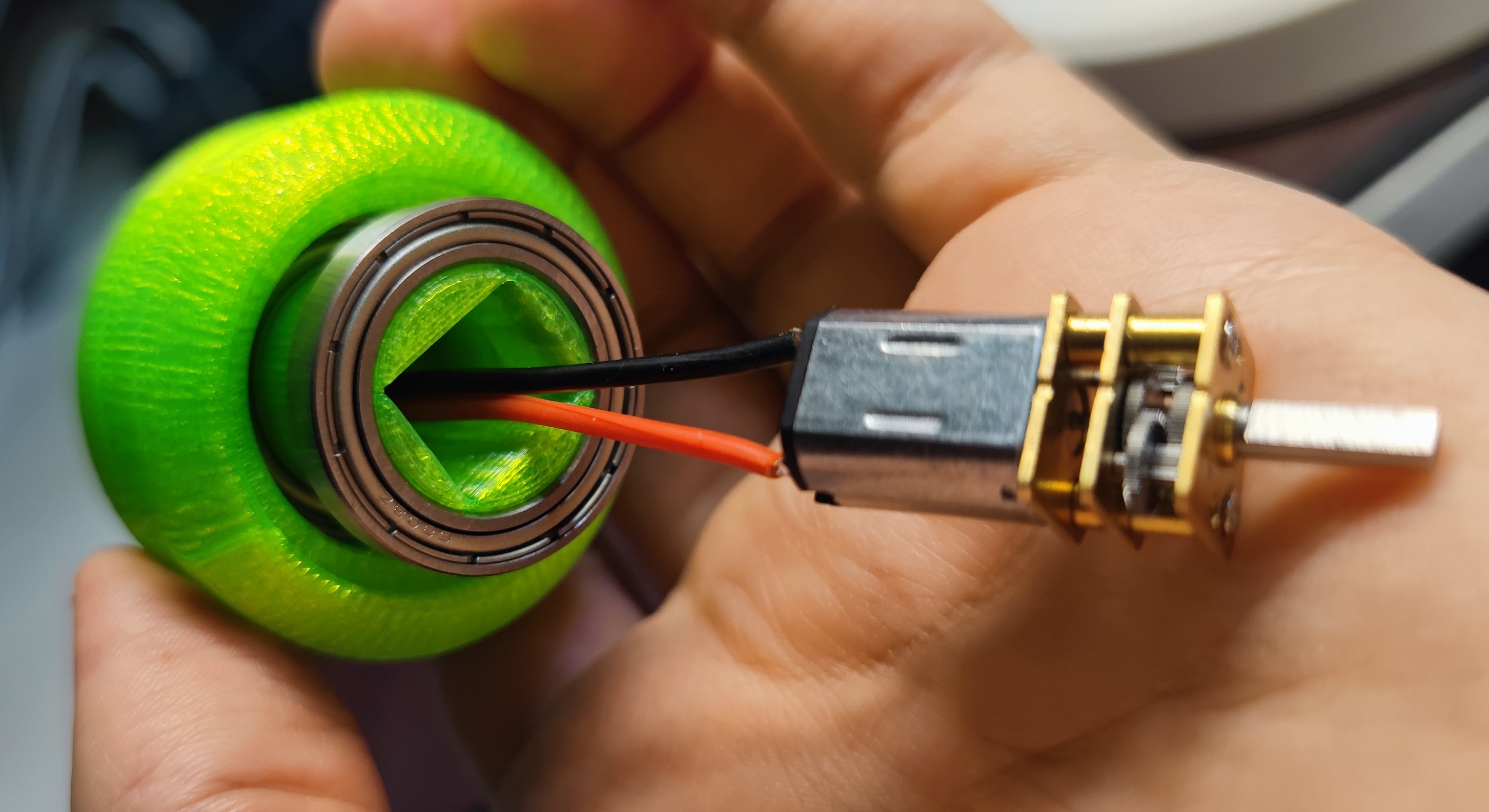
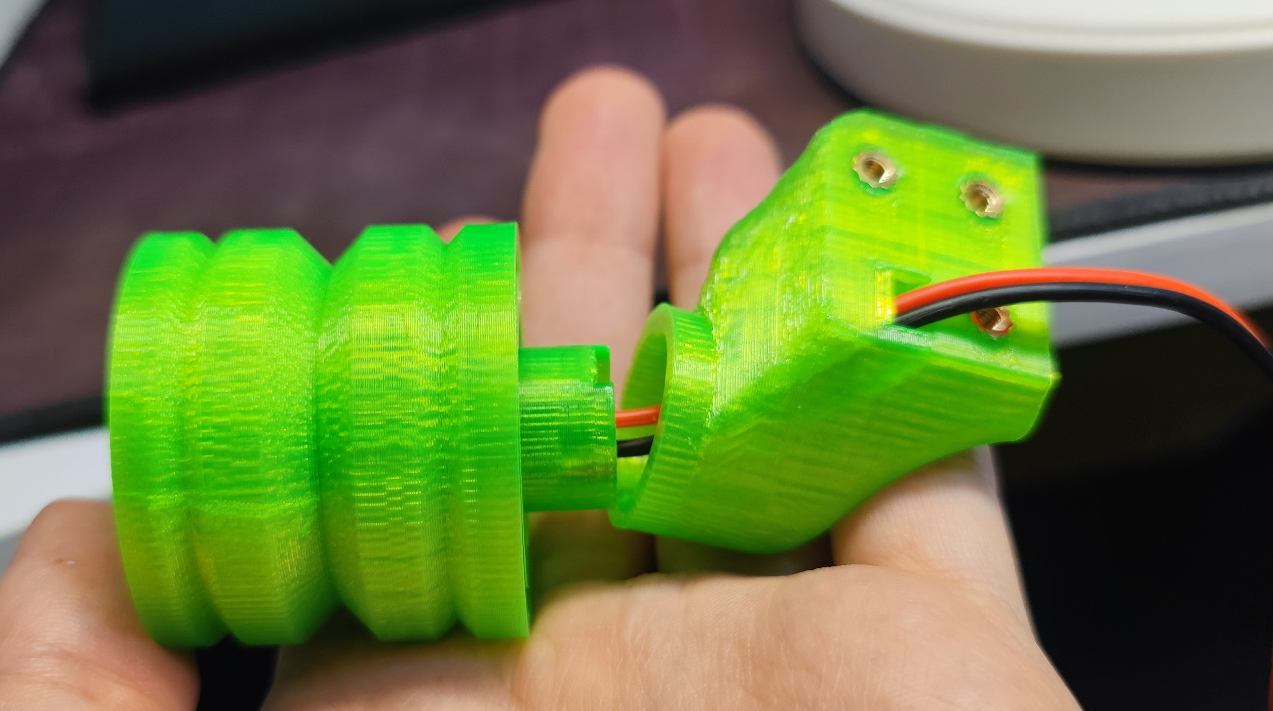
Кронштейн особого внимания не заслуживает, был смоделирован с прицелом на референсный дизайн и стыковку с корпусом. Крепление к колесу и корпусу на болтах и впаечных резьбовых втулках. Внутри канал для прокладывания кабеля питание моторчика.
Так как корпус в дизайне явно занял бы много времени временно была смоделирована плоская платформа для крепления и тестирования - и здесь получилось с первого раза попасть в допуски, платформа оказалась достаточно устойчивой:
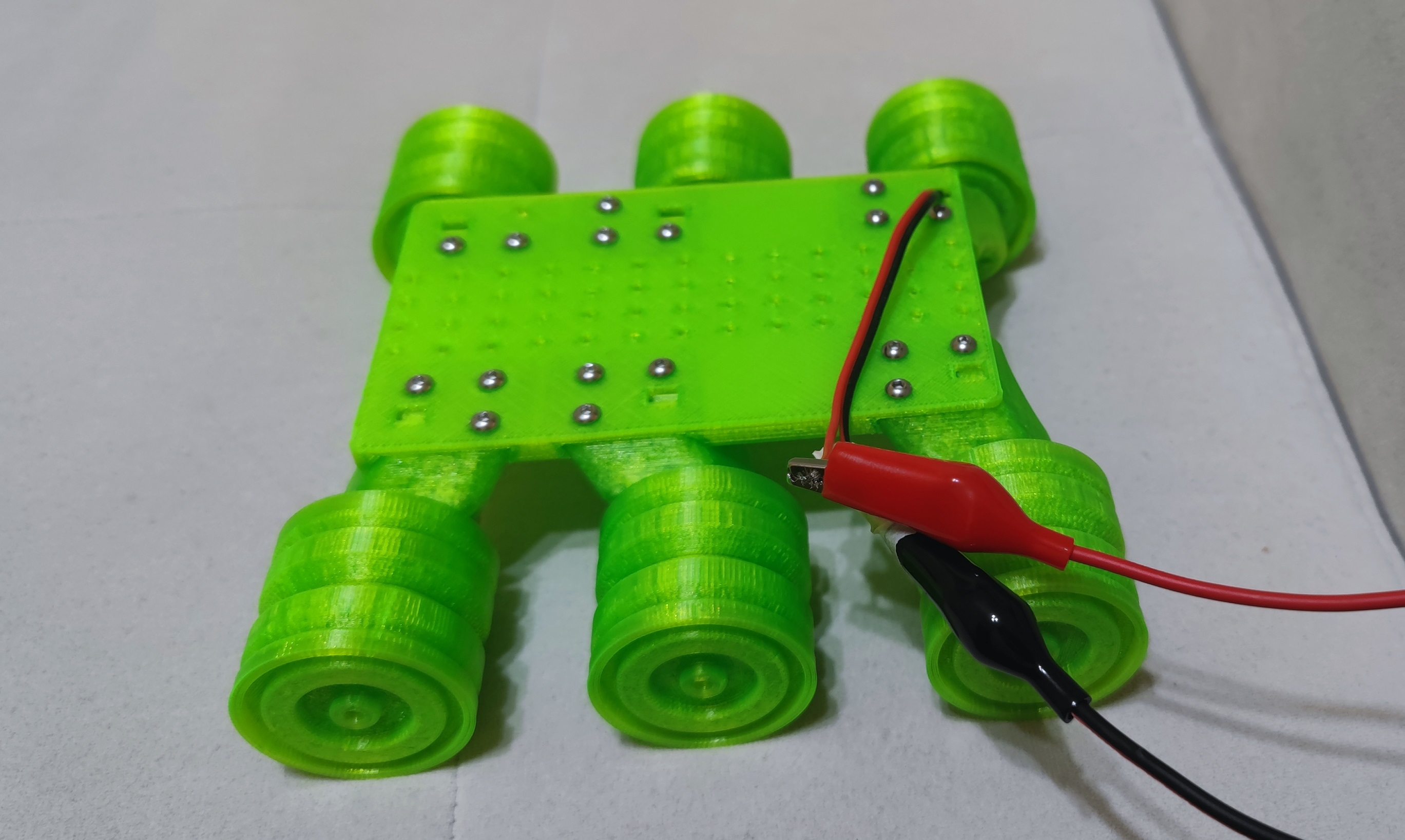
Концепт вполне себе рабочий и даже внешне мне нравится. Статья получилась короткой, хотя на деле было несколько итераций проектирования, печати и переизобретения.
Спасибо всем тем ребятам, что выкладывают точные 3д модели (подшипников, моторчиков и прочих готовых компонентов) в открытый доступ - только благодаря ним удалось сократить огромное количество часов. Основной источник таких моделей - grabcad. Ну и без САПР никуда - Fusion 360, на который я перешёл с SolidWorks, очень даже простая в освоений, но весьма техетлогичная софтина.
Эволюция версий выглядит примерно так:

Комментариев пока нет
-

Проект Наблюдатель
Проект приурочен к хеллоуину - это статуя одноглазого ктулху с механизированным… -

Универсальный AI Telegram Bot
Хотите в пару действий запустить собственного AI бота для Telegram? -

Анализ истории просмотров Youtube
Задумывались, сколько времени вы проводите за просмотром видео? Давайте считать. -

Image2model с tripo3d и Blender
Иногда хочется, чтобы нарисованный или сгенерированный персонаж стал настоящим -

Локальный эмулятор Telegram
Писали ли вы когда-нибудь телеграм ботов? -

Реанимируем основание вешалок
Есть дома пара вешалок с плечиками, на которых удобно располагается одежда для…